


Introduction & System Overview
In the fast-paced world of fintech, clarity is currency. When architecting a Mobile Banking App, understanding the interactions between users, administrators, and external systems is critical for security and usability. A Use Case Diagram provides that high-level view, mapping out who does what within the system boundaries. For this tutorial, we will leverage VPasCode, a powerful diagram-as-code tool, to generate a professional Use Case Diagram using PlantUML. This approach ensures your documentation remains version-controlled and easy to update.

Complete Diagram & Full Source Code
Before diving into the step-by-step breakdown, here is the complete, rendered diagram. You can see how the Customer, Bank Admin, and Payment Gateway interact with the core banking features like Login, Transfer Money, and Pay Bills.
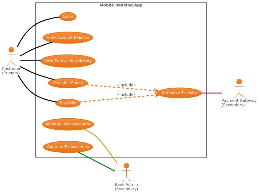
Below is the complete PlantUML source code used to generate this diagram. Copy this directly into the VPasCode editor to start your own project.
@startuml
!theme aws-orange
left to right direction
actor "Customer\n(Primary)" as cust
actor "Bank Admin\n(Secondary)" as admin
actor "Payment Gateway\n(Secondary)" as gateway

rectangle "Mobile Banking App" {
  usecase "Login" as UC1
  usecase "View Account Balance" as UC2
  usecase "View Transaction History" as UC3
  usecase "Transfer Money" as UC4
  usecase "Pay Bills" as UC5
  usecase "Authorize Transfer" as UC6
  usecase "Manage User Accounts" as UC7
  usecase "Approve Transactions" as UC8
}

cust -[#black]- UC1
cust -[#black]- UC2
cust -[#black]- UC3
cust -[#black]- UC4
cust -[#black]- UC5
UC4 ...> UC6 : <<include>>
UC6 -[#crimson]- gateway
UC7 -[#goldenrod]- admin
UC8 -[#green]- admin
UC5 ...> UC6 : <<include>>
@endumlStep-by-Step Breakdown & Thought Process
Building a diagram-as-code requires a logical flow. Here is how I approached designing this Mobile Banking Use Case Diagram using VPasCode.
1. Setting the Foundation and Theme
I start by defining the diagram’s orientation and visual identity. For a finance application, a clean, professional look is essential. I used the aws-orange theme to give it a modern, corporate feel, and set the direction to flow naturally from left to right.
!theme aws-orange
left to right direction
2. Defining the Actors
Next, I identified the key stakeholders. In mobile banking, there are typically primary users (customers) and secondary systems or administrators. I defined the Customer, Bank Admin, and Payment Gateway. Using the actor keyword allows me to name them and assign aliases for cleaner code later.
actor "Customer\n(Primary)" as cust
actor "Bank Admin\n(Secondary)" as admin
actor "Payment Gateway\n(Secondary)" as gateway
3. Establishing System Boundaries
To clearly separate internal functionality from external entities, I wrapped the use cases in a rectangle labeled “Mobile Banking App”. This visual boundary is crucial for stakeholders to understand what is inside the system scope.
rectangle "Mobile Banking App" {
  usecase "Login" as UC1
  usecase "View Account Balance" as UC2
  usecase "View Transaction History" as UC3
  usecase "Transfer Money" as UC4
  usecase "Pay Bills" as UC5
  usecase "Authorize Transfer" as UC6
  usecase "Manage User Accounts" as UC7
  usecase "Approve Transactions" as UC8
}
4. Mapping Relationships and Includes
This is where the logic of the finance workflow comes alive. I connected the Customer to core functions using solid lines. Crucially, I used the <<include>> relationship for Transfer Money and Pay Bills. This signifies that authorizing a transfer is a mandatory step within those processes.
cust -[#black]- UC1
cust -[#black]- UC4
UC4 ...> UC6 : <<include>>
5. Styling Connections
To improve readability, I added color coding to the connections. For instance, the Payment Gateway connection uses a crimson line to highlight security-sensitive transactions, while the Admin connections use goldenrod and green to distinguish between account management and transaction approval.
UC6 -[#crimson]- gateway
UC7 -[#goldenrod]- admin
UC8 -[#green]- admin
Key Takeaways & Best Practices
When creating Use Case Diagrams with PlantUML in VPasCode, keep these tips in mind:
- Use Aliases for Cleanliness: Assign aliases like
as custto keep your relationship lines short and readable. - Visual Hierarchy: Use themes and line colors to differentiate between primary user actions and backend administrative tasks.
- Modularity: Group related use cases inside a
rectangleto clearly define your system boundary, which is especially important in complex finance architectures.
Try It Yourself with VPasCode
Ready to model your own finance workflows? VPasCode makes diagramming as simple as writing code. You can edit this diagram instantly in your browser.
VPasCode Editor (Free to use): https://vpascode.com/editor
VPasCode Home Page: https://vpascode.com/