


Introduction: Visualizing Complex Government Workflows
In the realm of Civic Identity Management, clarity is not just a design preference—it is a regulatory necessity. Government systems like Passport Application Processing involve intricate interactions between citizens, digital portals, backend services, and secure databases. When architects and developers attempt to document these flows using traditional static diagrams, the documentation often becomes outdated the moment the system evolves. This is where the diagram-as-code paradigm shines.
By leveraging PlantUML within the VPasCode environment, teams can create living, executable documentation that stays in sync with the system architecture. This tutorial focuses on a critical government workflow: the end-to-end processing of a passport application. We will explore how to model the submission, validation, biometric verification, and payment processing phases, including robust error handling for alternative flows.
Using VPasCode, you can prototype this architecture instantly in the browser without installing Java or configuring build tools. This approach ensures that your sequence diagrams remain accurate, shareable, and easily editable by stakeholders across the development lifecycle.
Understanding the Model: Purpose, Scope & Problem Framing
Diagram Abstraction & Representation
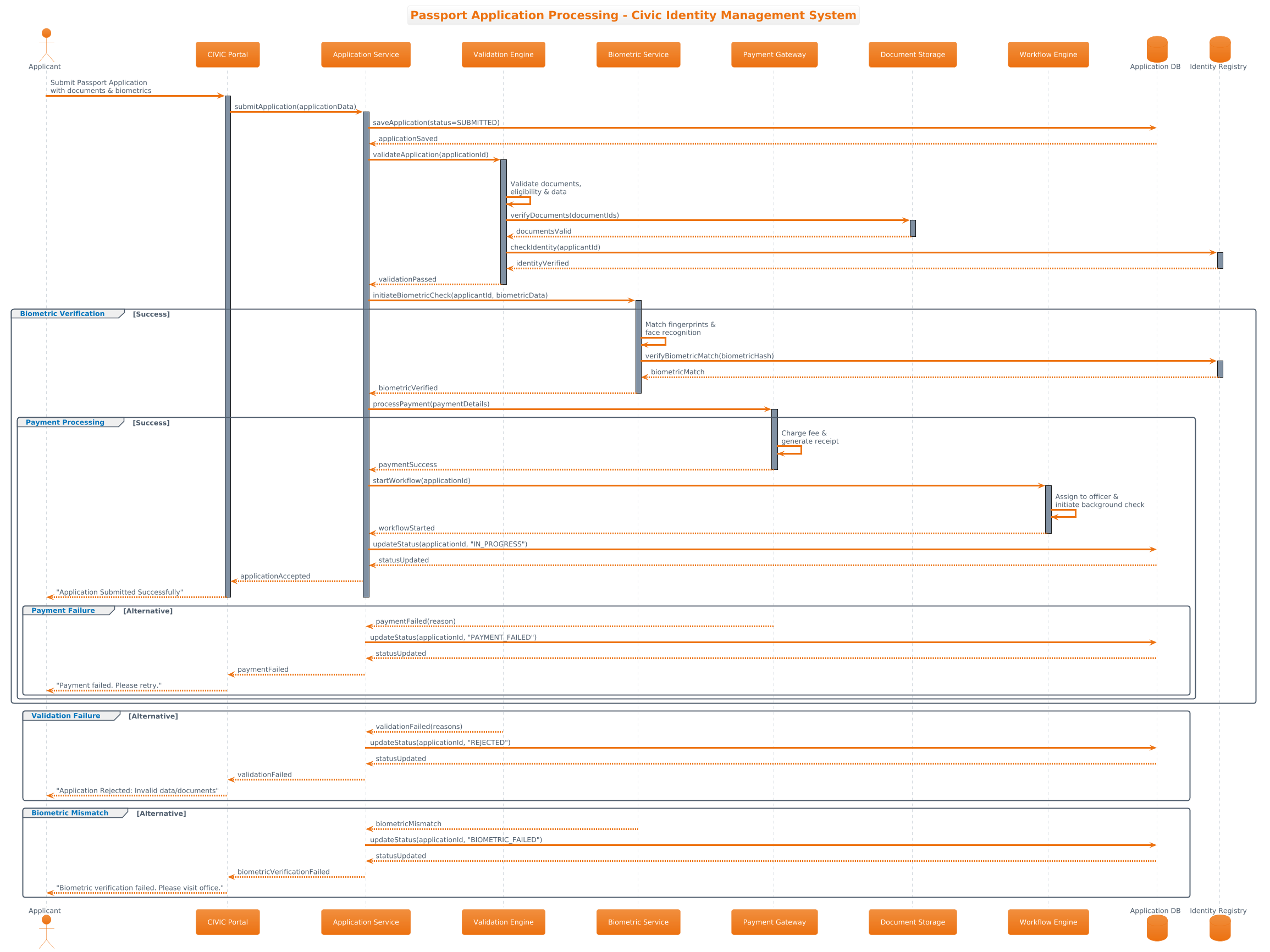
A Sequence Diagram is the ideal tool for modeling this scenario because it captures the temporal order of interactions. Unlike a class diagram that shows structure, or a flowchart that shows logic, a sequence diagram explicitly maps the lifelines of participants (actors, services, databases) and the messages passed between them over time.
In this specific model, we represent the Civic Identity Management System. The diagram breaks down the process into distinct phases:
- Actors: The human initiating the request (Applicant) and the interface they use (CIVIC Portal).
- Services: The logical processing units (Application Service, Validation Engine, Biometric Service).
- Persistence: The data stores (Application DB, Identity Registry, Document Storage).
Target Domain Scope & Scenario
This model is scoped to the application intake and initial processing phase. It does not cover the final printing or mailing of the physical passport. Instead, it focuses on the critical decision points: Does the data validate? Does the biometric match? Is the payment successful? By isolating these flows, the diagram highlights the system’s resilience and error handling capabilities.
Key Takeaways & Educational Insights
By building this diagram, you will gain insight into:
- How to structure a complex multi-service transaction using PlantUML lifelines.
- How to model combined fragments (groups) to represent alternative paths like payment failures or biometric mismatches.
- How to apply visual themes (like
aws-orange) to align with enterprise branding standards.
Complete Diagram & Full Source Code
Below is the complete blueprint for the Passport Application Processing sequence diagram. You can view the rendered output immediately by pasting this code into the VPasCode editor.
@startuml
!theme aws-orange

title Passport Application Processing - Civic Identity Management System

/'
This sequence diagram illustrates the end-to-end processing of a passport application
within the Civic Identity Management System. It covers the submission, validation,
biometric verification, payment processing, and final approval or rejection of the application.
Alternative flows are represented using combined fragments for successful submission,
validation failure, payment failure, and biometric mismatch scenarios.
'/

actor "Applicant" as App
participant "CIVIC Portal" as Portal
participant "Application Service" as AppSvc
participant "Validation Engine" as ValEng
participant "Biometric Service" as BioSvc
participant "Payment Gateway" as PayGW
participant "Document Storage" as DocStore
participant "Workflow Engine" as WfEng
database "Application DB" as AppDB
database "Identity Registry" as IdReg

App -> Portal: Submit Passport Application\nwith documents & biometrics
activate Portal

Portal -> AppSvc: submitApplication(applicationData)
activate AppSvc

AppSvc -> AppDB: saveApplication(status=SUBMITTED)
AppDB --> AppSvc: applicationSaved

AppSvc -> ValEng: validateApplication(applicationId)
activate ValEng

group Validation Check [Success]
    ValEng -> ValEng: Validate documents,\neligibility & data
    ValEng -> DocStore: verifyDocuments(documentIds)
    activate DocStore
    DocStore --> ValEng: documentsValid
    deactivate DocStore

    ValEng -> IdReg: checkIdentity(applicantId)
    activate IdReg
    IdReg --> ValEng: identityVerified
    deactivate IdReg

    ValEng --> AppSvc: validationPassed
    deactivate ValEng

    AppSvc -> BioSvc: initiateBiometricCheck(applicantId, biometricData)
    activate BioSvc

    group Biometric Verification [Success]
        BioSvc -> BioSvc: Match fingerprints &\nface recognition
        BioSvc -> IdReg: verifyBiometricMatch(biometricHash)
        activate IdReg
        IdReg --> BioSvc: biometricMatch
        deactivate IdReg

        BioSvc --> AppSvc: biometricVerified
        deactivate BioSvc

        AppSvc -> PayGW: processPayment(paymentDetails)
        activate PayGW

        group Payment Processing [Success]
            PayGW -> PayGW: Charge fee &\ngenerate receipt
            PayGW --> AppSvc: paymentSuccess
            deactivate PayGW

            AppSvc -> WfEng: startWorkflow(applicationId)
            activate WfEng
            WfEng -> WfEng: Assign to officer &\ninitiate background check
            WfEng --> AppSvc: workflowStarted
            deactivate WfEng

            AppSvc -> AppDB: updateStatus(applicationId, "IN_PROGRESS")
            AppDB --> AppSvc: statusUpdated

            AppSvc --> Portal: applicationAccepted
            Portal --> App: "Application Submitted Successfully"
            deactivate Portal
            deactivate AppSvc

        group Payment Failure [Alternative]
            PayGW --> AppSvc: paymentFailed(reason)
            deactivate PayGW

            AppSvc -> AppDB: updateStatus(applicationId, "PAYMENT_FAILED")
            AppDB --> AppSvc: statusUpdated

            AppSvc --> Portal: paymentFailed
            Portal --> App: "Payment failed. Please retry."
            deactivate Portal
            deactivate AppSvc
        end
    end
end

group Validation Failure [Alternative]
    ValEng --> AppSvc: validationFailed(reasons)
    deactivate ValEng

    AppSvc -> AppDB: updateStatus(applicationId, "REJECTED")
    AppDB --> AppSvc: statusUpdated

    AppSvc --> Portal: validationFailed
    Portal --> App: "Application Rejected: Invalid data/documents"
    deactivate Portal
    deactivate AppSvc
end

group Biometric Mismatch [Alternative]
    BioSvc --> AppSvc: biometricMismatch
    deactivate BioSvc

    AppSvc -> AppDB: updateStatus(applicationId, "BIOMETRIC_FAILED")
    AppDB --> AppSvc: statusUpdated

    AppSvc --> Portal: biometricVerificationFailed
    Portal --> App: "Biometric verification failed. Please visit office."
    deactivate Portal
    deactivate AppSvc
end
@endumlStep-by-Step Architectural Walkthrough
Now that you have the full blueprint, let’s break down how to construct this diagram logically. We will build this in four phases, moving from setup to complex interaction flows.
Phase 1: Canvas Configuration & Layout Directives
Before defining any participants, we set the visual theme and context. This ensures consistency with enterprise branding and provides immediate documentation context.
First, apply the aws-orange theme to match typical cloud infrastructure styling:
!theme aws-orangeNext, define the title and add a description block. The description uses the /' and '/ syntax for comments, which are rendered as text within the diagram:
title Passport Application Processing - Civic Identity Management System

/'
This sequence diagram illustrates the end-to-end processing...
'/
Phase 2: Declaring Core Entities, Actors, and Boundaries
Define the participants that will interact. In PlantUML, we distinguish between human actors, system participants, and persistent storage.
Use the actor keyword for the human user and the participant keyword for software components. Databases are explicitly marked with database for semantic clarity:
actor "Applicant" as App
participant "CIVIC Portal" as Portal
database "Application DB" as AppDB
Note the use of aliases (e.g., as App). This allows you to use shorter identifiers in the interaction lines, keeping the diagram code clean.
Phase 3: Mapping Data Flows & Key Interactions
Now we connect the lifelines. Use solid arrows (->) for synchronous calls and dashed arrows (-->) for returns. Activate and deactivate lifelines to show when a component is busy processing.
For the initial submission:
App -> Portal: Submit Passport Application
activate Portal

Portal -> AppSvc: submitApplication(applicationData)
activate AppSvc
This establishes the primary timeline. You can see how the AppSvc takes ownership of the request and interacts with the database to persist the initial state.
Phase 4: Grouping, Annotations & Visual Polish
Complex systems require handling exceptions. In PlantUML, we use group to represent combined fragments (like alt or opt blocks). This visualizes alternative flows without cluttering the main timeline.
For example, the Payment Failure flow is encapsulated in a group:
group Payment Failure [Alternative]
    PayGW --> AppSvc: paymentFailed(reason)
    AppSvc -> AppDB: updateStatus(applicationId, "PAYMENT_FAILED")
end
This structure allows the diagram to show success and failure paths side-by-side, making the system’s robustness immediately apparent to stakeholders.
Syntax & Keyword Deep Dive
To master this diagram, you must understand the specific PlantUML syntax features used. Here is a breakdown of the critical keywords:
actor: Defines a human user or external system interacting with the software. In this diagram, it represents the Applicant.participant: Represents a class, component, or service within the system architecture (e.g., CIVIC Portal, Application Service).database: Specifically styles the lifeline to indicate persistent storage (e.g., Application DB, Identity Registry).->(Solid Arrow): Indicates a synchronous message or request sent from one participant to another.-->(Dashed Arrow): Indicates a return message or response from the target back to the source.activate/deactivate: These control the vertical activation bar on a lifeline, showing when a participant is actively processing a request.group: Used to create combined fragments (equivalent toalt,opt, orloopin some UML tools). It visually boxes alternative flows or loops, such as the Payment Failure scenario./' ... '/: The comment syntax in PlantUML that renders as text within the diagram area, used here for the diagram description.
Best Practices & Pitfalls to Avoid
When modeling government or enterprise workflows, clarity and maintainability are paramount. Follow these best practices to ensure your diagrams remain effective.
- Keep Lifelines Meaningful: Do not create a new participant for every single method call. Group related services under logical participants (e.g., Validation Engine handles all validation logic).
- Visualize Failure Paths: A diagram that only shows the “Happy Path” is misleading. Always use
groupblocks to represent error handling, such as Biometric Mismatch or Payment Failure. - Use Descriptive Aliases: While
actor "Applicant" as Appis concise, ensure the alias matches the context. If the diagram grows, long names likeApplicantcan be used directly to avoid confusion. - Leverage Themes: Use
!themedirectives to maintain consistency across your documentation suite. Theaws-orangetheme used here aligns with modern cloud infrastructure aesthetics.
Start Building Sequence Diagrams Faster with VPasCode
Instantly prototype and render complex government workflows with zero installation, testing your syntax and visual themes directly in your browser.