


In the high-stakes environment of Retail Banking, clarity in user interaction flows is not just a design preference—it is a compliance and security necessity. When a customer activates Overdraft Protection, they are engaging with a multi-service architecture that spans authentication, credit scoring, account management, and notification systems. A single misstep in this workflow can lead to financial discrepancies or security vulnerabilities.

Visual modeling is critical here. Sequence diagrams provide the temporal logic needed to verify that security checks occur before financial commitments are made. By using a diagram-as-code approach with PlantUML inside VPasCode, software architects can rapidly prototype these flows, validate edge cases like credit denials, and generate living documentation that stays synchronized with the codebase.
This tutorial demonstrates how to build a professional-grade sequence diagram for an Overdraft Protection Activation scenario. We will leverage VPasCode‘s instant browser-based rendering to test interaction paths without needing to install Java or configure local dependencies.
Understanding the Model: Purpose, Scope & Problem Framing
Before writing a single line of syntax, it is essential to understand the architectural abstraction we are modeling.
Diagram Abstraction & Representation
A Sequence Diagram is the primary tool for modeling runtime interactions. Unlike static class diagrams, sequence diagrams capture the when and how of system behavior. In this specific model, we represent the chronological exchange of messages between the Customer and various backend services. Each vertical line, known as a lifeline, represents an entity’s existence over time, while horizontal arrows represent synchronous or asynchronous messages.
Target Domain Scope & Scenario
The scope of this diagram is strictly limited to the Overdraft Protection Activation workflow. It does not cover the broader banking ledger or transaction processing. The boundaries are defined as follows:
- Initiator: The Customer via the Mobile App.
- Security Boundary: Authentication Service validates the session before any account data is accessed.
- Business Logic: Credit Check Service determines eligibility before the Overdraft Manager creates the facility.
- Feedback Loop: Notification Service informs the user of the outcome.
Key Takeaways & Educational Insights
By constructing this model, you will gain insights into:
- How to structure multi-service dependencies in a banking context.
- How to use PlantUML combined fragments (
alt,else) to map complex decision trees. - How to manage activation and deactivation lifelines to visualize service load.
Complete Diagram & Full Source Code
Below is the complete blueprint for the Overdraft Protection Activation flow. You can copy this code directly into the VPasCode editor to see the live rendering.
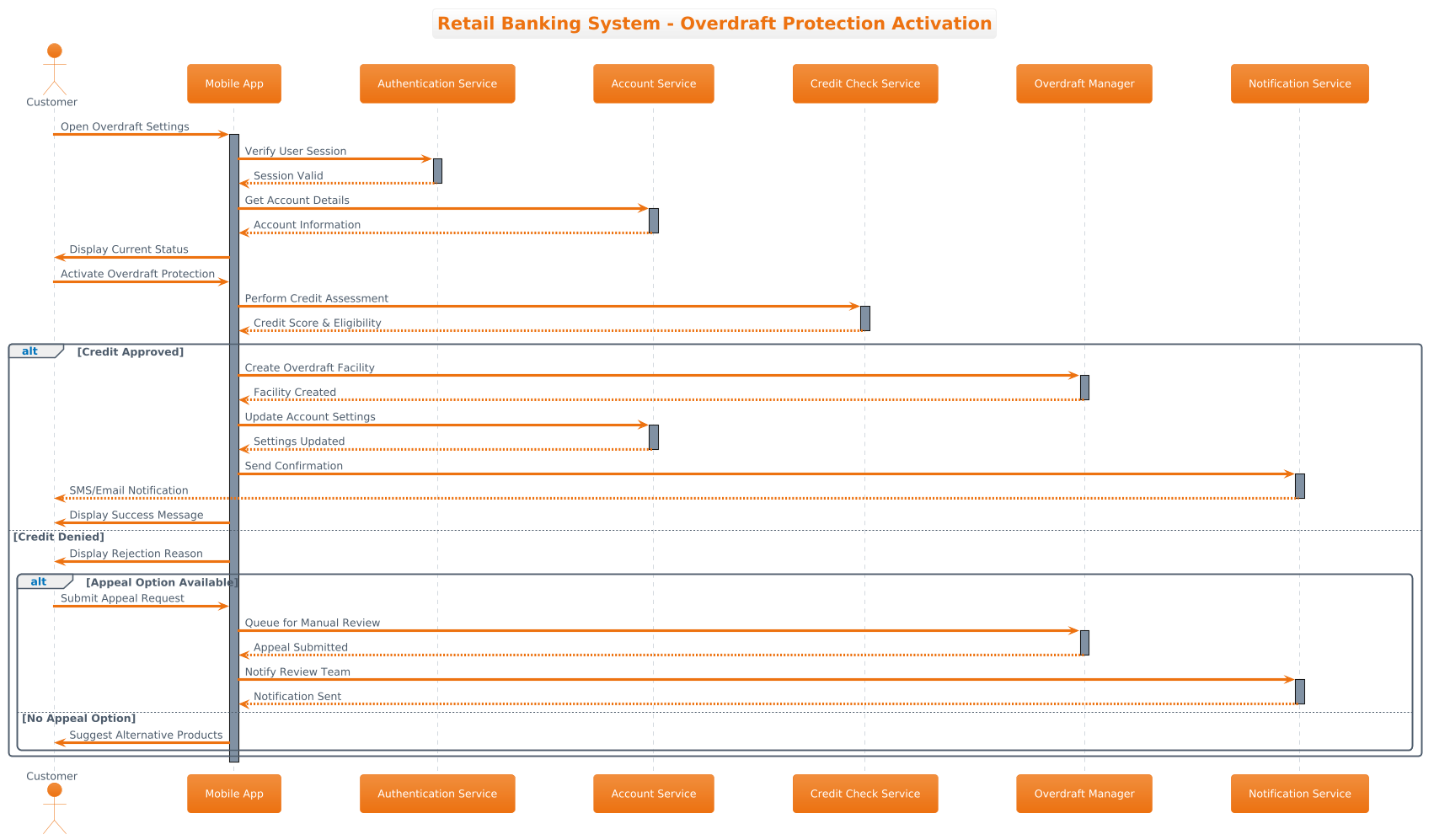
@startuml
!theme aws-orange

title Retail Banking System - Overdraft Protection Activation

actor "Customer" as customer
participant "Mobile App" as app
participant "Authentication Service" as authService
participant "Account Service" as accountService
participant "Credit Check Service" as creditCheck
participant "Overdraft Manager" as overdraftMgr
participant "Notification Service" as notifier

customer -> app: Open Overdraft Settings
activate app
app -> authService: Verify User Session
activate authService
authService --> app: Session Valid
deactivate authService

app -> accountService: Get Account Details
activate accountService
accountService --> app: Account Information
deactivate accountService

app -> customer: Display Current Status
customer -> app: Activate Overdraft Protection

app -> creditCheck: Perform Credit Assessment
activate creditCheck
creditCheck --> app: Credit Score & Eligibility
deactivate creditCheck

alt Credit Approved
    app -> overdraftMgr: Create Overdraft Facility
    activate overdraftMgr
    overdraftMgr --> app: Facility Created
    deactivate overdraftMgr

    app -> accountService: Update Account Settings
    activate accountService
    accountService --> app: Settings Updated
    deactivate accountService

    app -> notifier: Send Confirmation
    activate notifier
    notifier --> customer: SMS/Email Notification
    deactivate notifier

    app -> customer: Display Success Message
else Credit Denied
    app -> customer: Display Rejection Reason
    alt Appeal Option Available
        customer -> app: Submit Appeal Request
        app -> overdraftMgr: Queue for Manual Review
        activate overdraftMgr
        overdraftMgr --> app: Appeal Submitted
        deactivate overdraftMgr

        app -> notifier: Notify Review Team
        activate notifier
        notifier --> app: Notification Sent
        deactivate notifier
    else No Appeal Option
        app -> customer: Suggest Alternative Products
    end
end

deactivate app
@endumlStep-by-Step Architectural Walkthrough
Building a robust sequence diagram requires a phased approach. We will construct this model from the canvas configuration down to the specific interaction logic.
Phase 1: Canvas Configuration & Layout Directives
Every PlantUML diagram begins with initialization directives. These set the visual theme and the overall title, ensuring the diagram aligns with your organization’s branding standards.
In this example, we apply the aws-orange theme to match a cloud-native infrastructure aesthetic, which is common in modern fintech architectures. We also define the title directive to provide immediate context.
!theme aws-orange

title Retail Banking System - Overdraft Protection Activation
Phase 2: Declaring Core Entities, Actors, and Boundaries
Next, we define the participants. In a sequence diagram, participants can be human actors or system components. We use the actor keyword for human users and participant for software services.
Notice how we assign aliases (e.g., as customer). This allows us to reference the actor later in the message flow without repeating the full label, keeping the code clean.
actor "Customer" as customer
participant "Mobile App" as app
participant "Authentication Service" as authService
Phase 3: Mapping Data Flows & Key Interactions
With the actors defined, we map the primary interaction flow using arrows. The syntax Actor -> Service: Message denotes a synchronous call. To visualize the lifecycle of a service, we use activate and deactivate keywords. This creates the vertical bar (activation bar) on the lifeline, indicating when the service is busy processing.
customer -> app: Open Overdraft Settings
activate app
app -> authService: Verify User Session
activate authService
Phase 4: Grouping, Annotations & Visual Polish
Real-world banking flows are rarely linear. They involve conditional logic based on risk assessment. We use the alt (alternative) combined fragment to handle the Credit Check outcome. This groups the “Credit Approved” and “Credit Denied” paths.
Furthermore, we nest another alt block within the denial path to handle the Appeal Option, demonstrating how to manage complex, multi-level decision trees within a single diagram.
alt Credit Approved
    app -> overdraftMgr: Create Overdraft Facility
    ...
else Credit Denied
    ...
end
Syntax & Keyword Deep Dive
To master PlantUML in VPasCode, you must understand the specific keywords that drive the visualization logic.
actor: Defines a human user or external entity interacting with the system. It typically appears on the far left of the diagram.participant: Defines a system component, service, or database. It represents the backend infrastructure.->: Represents a synchronous message call. The sender waits for a response before continuing.activate/deactivate: These keywords control the visual representation of the lifeline.activatestarts the solid bar, anddeactivateends it, showing the duration of the service’s involvement.alt/else/end: These create combined fragments.altstarts an alternative block,elsedefines a fallback condition, andendcloses the block. This is essential for modeling error handling and branching logic.title: Sets the main heading of the diagram, providing immediate context to the viewer.
Best Practices & Pitfalls to Avoid
When modeling complex banking workflows, adhering to best practices ensures your diagrams remain maintainable and readable.
- Modularize Complex Flows: If a sequence becomes too long (e.g., over 50 lines), consider breaking it into multiple diagrams focusing on specific sub-processes like “Authentication” or “Credit Approval”.
- Consistent Naming Conventions: Use clear, descriptive names for participants. Avoid abbreviations like
svcin favor ofauthServiceto ensure clarity for new developers. - Manage Visual Complexity: Use
altblocks judiciously. Too many nestedaltblocks can make the diagram hard to read. Ensure every condition has a clear exit path. - Theme Consistency: Use VPasCode themes like
aws-orangeto maintain a professional look. Consistent styling helps stakeholders recognize diagrams as part of the same documentation suite.
Try It Yourself with VPasCode
Ready to prototype your own financial architecture flows? VPasCode offers an instant browser-based environment to write, render, and refine your PlantUML diagrams without any local installation.
Start Building Sequence Diagrams Faster with VPasCode
Experience instant live browser preview and interactive syntax testing for your banking workflows without installing any tools.