


In the fast-paced world of financial technology, clarity in system interactions is not just a convenience—it is a regulatory and operational necessity. The Automated Clearing House (ACH) system serves as the backbone for electronic payments in many regions, handling everything from payroll deposits to bill payments. When modeling a Direct Debit Authorization workflow, architects must precisely define how funds are requested, verified, and confirmed across multiple banking entities.

Visual modeling is critical here because a single miscommunication between the Merchant System, the ACH Processor, and the Receiving Bank can lead to failed transactions or compliance breaches. Using PlantUML with VPasCode allows teams to adopt a diagram-as-code approach. This method enhances architectural clarity by treating diagrams as versioned, text-based documentation that can be rapidly prototyped and tested in the browser without installing local dependencies.
This guide demonstrates how to construct a professional Sequence Diagram that captures the temporal flow of authorization requests, identity verification, and alternative error paths within an ACH environment.
Understanding the Model: Purpose, Scope & Problem Framing
Diagram Abstraction & Representation
A Sequence Diagram is the ideal tool for modeling time-dependent interactions between system components. Unlike static architecture diagrams, this notation focuses on the flow of messages over time. In this specific model, we represent:
- Lifelines: Vertical lines representing the lifespan of each participant (e.g., Account Holder, Merchant, Banks).
- Messages: Horizontal arrows indicating synchronous requests (e.g., “Submit direct debit request”) and asynchronous responses.
- Activation Bars: Rectangular boxes showing when a participant is actively processing a task.
Target Domain Scope & Scenario
The scope of this diagram is strictly limited to the Authorization Phase of a Direct Debit transaction. It does not cover the actual fund transfer settlement, which occurs later in the lifecycle. The boundaries include the Account Holder initiating the request, the Merchant validating it, and the banking network (ACH, Originating Bank, Receiving Bank) verifying the account status.
Key Takeaways & Educational Insights
By building this model, you will gain insights into:
- How to handle conditional logic using
altandelseblocks for identity verification. - The importance of
activateanddeactivatedirectives to visualize processing load. - How to structure complex multi-party financial flows for clear stakeholder communication.
Complete Diagram & Full Source Code
Below is the finished blueprint of the ACH Direct Debit Authorization flow. You can view the rendered output immediately by pasting the code into the VPasCode editor.
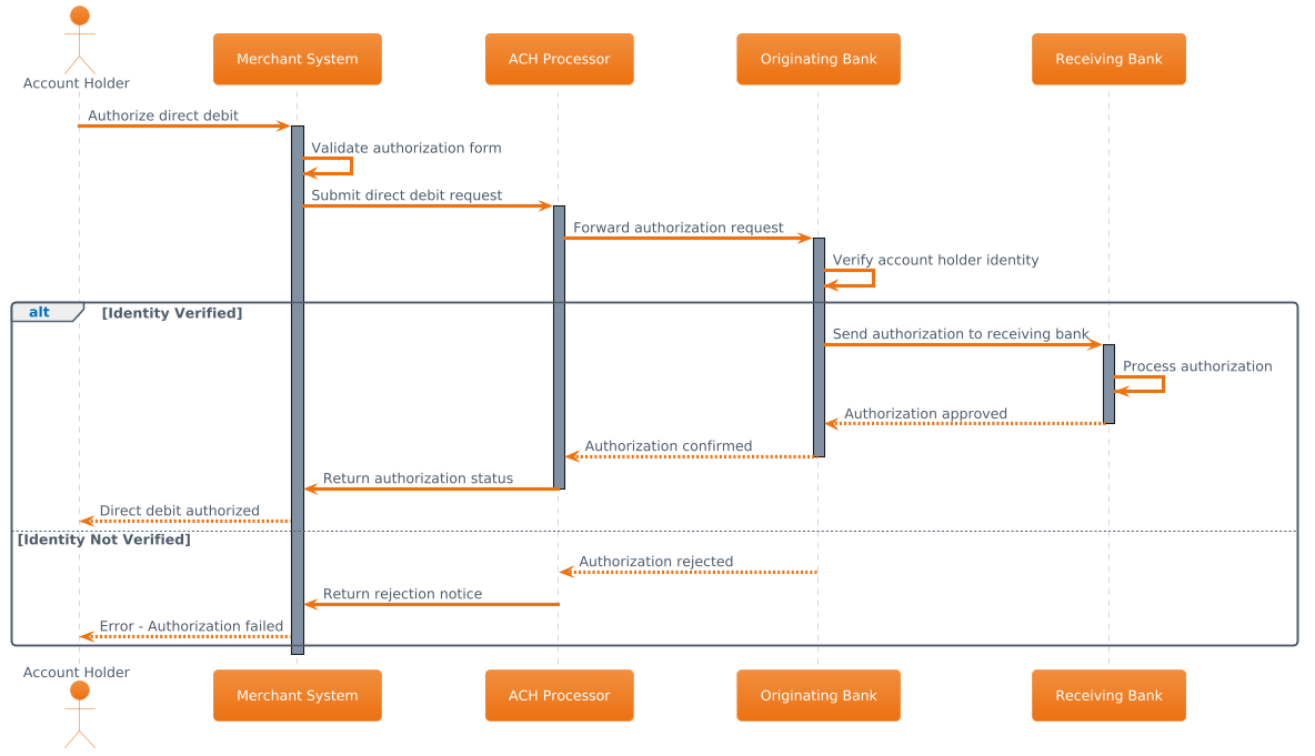
@startuml
!theme aws-orange

actor "Account Holder" as AH
participant "Merchant System" as MS
participant "ACH Processor" as ACH
participant "Originating Bank" as OB
participant "Receiving Bank" as RB

AH -> MS: Authorize direct debit
activate MS
MS -> MS: Validate authorization form
MS -> ACH: Submit direct debit request
activate ACH

ACH -> OB: Forward authorization request
activate OB
OB -> OB: Verify account holder identity

alt Identity Verified
    OB -> RB: Send authorization to receiving bank
    activate RB
    RB -> RB: Process authorization
    RB --> OB: Authorization approved
    deactivate RB

    OB --> ACH: Authorization confirmed
    deactivate OB

    ACH -> MS: Return authorization status
    deactivate ACH

    MS --> AH: Direct debit authorized
else Identity Not Verified
    OB --> ACH: Authorization rejected
    deactivate OB

    ACH -> MS: Return rejection notice
    deactivate ACH

    MS --> AH: Error - Authorization failed
end

deactivate MS
@endumlStep-by-Step Architectural Walkthrough
Building this diagram requires a structured approach to ensure the logic flows correctly from the user initiation to the banking confirmation. We will break this down into four distinct phases.
Phase 1: Canvas Configuration & Layout Directives
Before defining actors, we set the visual theme and rendering engine. This ensures the diagram aligns with modern UI standards and is easily readable.
Start by defining the diagram type and applying the theme:
@startuml
!theme aws-orange
The @startuml directive initializes the sequence diagram. The !theme aws-orange directive applies a specific color palette that matches the AWS-inspired branding often used in modern fintech dashboards.
Phase 2: Declaring Core Entities, Actors, and Boundaries
Next, we define the participants involved in the transaction. In PlantUML, we distinguish between human actors and system participants.
actor "Account Holder" as AH
participant "Merchant System" as MS
participant "ACH Processor" as ACH
participant "Originating Bank" as OB
participant "Receiving Bank" as RB
Here, actor is used for the human user, while participant represents software systems or banking entities. We assign short aliases (e.g., MS, ACH) to keep the message labels concise.
Phase 3: Mapping Data Flows & Key Interactions
This phase captures the core logic of the authorization. We use solid arrows (->) for synchronous requests and dashed arrows (-->) for responses.
AH -> MS: Authorize direct debit
activate MS
MS -> ACH: Submit direct debit request
activate ACH
We then introduce the conditional logic using the alt block. This is crucial for modeling the identity verification step.
alt Identity Verified
    OB -> RB: Send authorization to receiving bank
    activate RB
    RB -> RB: Process authorization
    RB --> OB: Authorization approved
    deactivate RB
else Identity Not Verified
    OB --> ACH: Authorization rejected
    deactivate OB
end
The alt keyword starts the alternative flow block, while else defines the failure path. Both blocks must be closed with end.
Phase 4: Grouping, Annotations & Visual Polish
Finally, we ensure all lifelines are properly deactivated to indicate the end of their active processing state. This prevents the diagram from looking cluttered with open activation bars.
ACH -> MS: Return authorization status
deactivate ACH

MS --> AH: Direct debit authorized
deactivate MS
@enduml
The @enduml tag closes the diagram definition.
Syntax & Keyword Deep Dive
Understanding the specific syntax of PlantUML allows you to extend this diagram for more complex scenarios. Below are the key keywords used in this ACH model:
actor: Defines a human user or external entity interacting with the system. Unlike participants, actors are typically drawn as stick figures.participant: Represents a system component, service, or database that processes requests.->(Arrow): Indicates a synchronous message where the sender waits for a response before continuing.-->(Dashed Arrow): Indicates an asynchronous message or a return response.activate/deactivate: These keywords control the activation bar (the rectangle on the lifeline).activatestarts the bar, showing the participant is busy.deactivateends it.alt/else/end: These create a combined fragment.altstarts the block,elsedefines the alternative condition, andendcloses the entire fragment structure.
Best Practices & Pitfalls to Avoid
To maintain high-quality documentation, follow these modeling guidelines:
- Keep Diagrams Modular: Do not try to model the entire payment lifecycle in one diagram. Focus on specific flows like Authorization, Settlement, or Reconciliation separately.
- Use Descriptive Labels: Ensure message labels clearly state the action (e.g., “Verify account holder identity” instead of just “Verify”).
- Manage Visual Complexity: If a sequence grows too long, consider breaking it into multiple diagrams or using the
groupdirective to visually separate logical sections. - Consistent Naming: Always use the same aliases (e.g.,
OBfor Originating Bank) throughout the file to avoid confusion.
Start Building PlantUML Sequence Diagrams Faster with VPasCode
Immediately test, preview, and customize this ACH Direct Debit diagram online in VPasCode without installing any tools or configuring local environments.