


In the complex landscape of telecommunications, clarity is paramount. Network Routing Systems serve as the backbone of data transmission, directing traffic across vast infrastructures with precision. However, documenting the functional requirements and user interactions of such a system can quickly become obscured by technical jargon. This is where visual modeling becomes critical.
A Use Case Diagram provides a high-level abstraction of system functionality, focusing on actors (users or external systems) and use cases (functional goals). By utilizing diagram-as-code with PlantUML in VPasCode, architects can rapidly prototype these models, ensuring that the boundary between the Network Routing System and its environment is clearly defined. This approach enhances architectural clarity, supports living technical documentation, and allows for instant validation of system requirements without the overhead of manual drawing tools.
Understanding the Model: Purpose, Scope & Problem Framing
Before diving into the syntax, it is essential to understand the abstraction being modeled. A Use Case Diagram is not a sequence of events; it is a map of what the system does and who interacts with it.
Diagram Abstraction & Representation
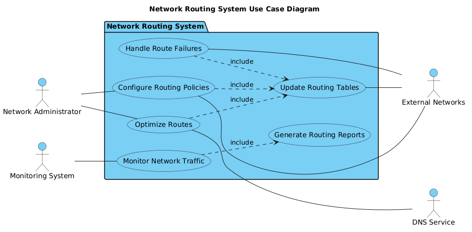
In this model, the Network Routing System is the central system boundary. Inside this boundary, we define specific functional goals like “Configure Routing Policies” or “Monitor Network Traffic.” Outside the boundary, we define Actors. Primary actors initiate the interactions (e.g., Network Administrator), while secondary actors support the system or receive output (e.g., External Networks). The lines connecting them represent associations, indicating that an actor can perform a specific use case.
Target Domain Scope & Scenario
This diagram specifically targets the operational scope of a telecommunications routing environment. It intentionally excludes low-level packet processing logic, focusing instead on the administrative and monitoring interfaces. The scope covers route configuration, traffic monitoring, table updates, and failure handling. Dependencies on external services like DNS are captured to show system integration points without cluttering the core routing logic.
Key Takeaways & Educational Insights
By constructing this model, you will gain insights into:
- System Boundaries: How to clearly delineate internal functionality from external dependencies.
- Actor Roles: Distinguishing between primary initiators and secondary support systems.
- Relationship Types: Understanding the difference between direct associations and included use cases (dependencies).
Complete Diagram & Full Source Code
Below is the complete blueprint for the Network Routing System Use Case Diagram. This single block of code contains all necessary directives, actor definitions, and relationship mappings.
@startuml
!include https://static.visual-paradigm.com/web/resources/plantuml-stdlib/themes/vp.puml

title Network Routing System Use Case Diagram

left to right direction

/'
This diagram illustrates the use cases for a Network Routing System that manages
the routing of data packets across network infrastructure. The system handles
route configuration, monitoring, and optimization to ensure efficient data
transmission. Primary actors include Network Administrators who configure and
manage routing policies, and Monitoring Systems that track network performance.
Secondary actors include External Networks that receive routed traffic and
DNS Services that provide name resolution support for routing decisions.
'/

actor "Network Administrator" as admin
actor "Monitoring System" as monitor

package "Network Routing System" {
    usecase "Configure Routing Policies" as UC1
    usecase "Monitor Network Traffic" as UC2
    usecase "Update Routing Tables" as UC3
    usecase "Optimize Routes" as UC4
    usecase "Handle Route Failures" as UC5
    usecase "Generate Routing Reports" as UC6
}

actor "External Networks" as external
actor "DNS Service" as dns

admin -- UC1
admin -- UC4
monitor -- UC2

UC1 ..> UC3 : include
UC2 ..> UC6 : include
UC4 ..> UC3 : include
UC5 ..> UC3 : include

UC1 -- external
UC3 -- external
UC4 --- dns
UC5 -- external
@endumlStep-by-Step Architectural Walkthrough
Phase 1: Canvas Configuration & Layout Directives
The first step in any PlantUML diagram is setting the stage. We begin by initializing the diagram engine and applying a professional theme. We also set the direction to ensure the flow of information is logical for the reader.
@startuml
!include https://static.visual-paradigm.com/web/resources/plantuml-stdlib/themes/vp.puml

title Network Routing System Use Case Diagram

left to right direction
The @startuml directive marks the beginning. The !include statement pulls in the Visual Paradigm theme for consistent styling. The title command adds a header, while left to right direction ensures actors on the left flow naturally into the system.
Phase 2: Declaring Core Entities, Actors, and Boundaries
Next, we define the actors and the system boundary. In PlantUML, actors are defined globally outside the package, while use cases are grouped within a package to represent the system boundary.
actor "Network Administrator" as admin
actor "Monitoring System" as monitor

package "Network Routing System" {
    usecase "Configure Routing Policies" as UC1
    usecase "Monitor Network Traffic" as UC2
    usecase "Update Routing Tables" as UC3
    usecase "Optimize Routes" as UC4
    usecase "Handle Route Failures" as UC5
    usecase "Generate Routing Reports" as UC6
}

actor "External Networks" as external
actor "DNS Service" as dns
Here, we use the actor keyword for external entities. We assign aliases (e.g., as admin) to keep the code concise. The package block creates the visual box representing the Network Routing System.
Phase 3: Mapping Data Flows & Key Interactions
With entities declared, we map the relationships. Primary actors connect to use cases using solid lines. We also define dependencies between use cases using the ..> syntax for includes.
admin -- UC1
admin -- UC4
monitor -- UC2

UC1 ..> UC3 : include
UC2 ..> UC6 : include
UC4 ..> UC3 : include
UC5 ..> UC3 : include
The -- operator denotes a direct association. The ..> operator denotes an include relationship, meaning one use case incorporates the functionality of another (e.g., Optimizing Routes requires Updating Routing Tables).
Phase 4: Grouping, Annotations & Visual Polish
Finally, we connect secondary actors and add a descriptive comment block. Secondary actors represent external systems that receive data or provide support.
UC1 -- external
UC3 -- external
UC4 --- dns
UC5 -- external
We use single lines (--) or double lines (---) to distinguish connection types if needed. The comment block at the top provides context for human readers without affecting the rendering logic.
Syntax & Keyword Deep Dive
Understanding the specific PlantUML syntax is crucial for mastering diagram-as-code. Here are the key keywords used in this Network Routing System model:
@startuml: Marks the beginning of the PlantUML code block.actor: Defines an external entity (person, system, or organization) interacting with the system.usecase: Defines a specific functional goal or action within the system boundary.package: Groups use cases together to visually represent the system boundary or subsystem.--: Represents an association line (solid line) between an actor and a use case...>: Represents an include relationship (dashed arrow), indicating that one use case depends on another./' ... '/: Defines a multi-line comment block for documentation purposes.
Best Practices & Pitfalls to Avoid
To maintain high-quality diagrams in VPasCode, adhere to these modeling best practices:
- Keep Diagrams Modular: Avoid cramming too many use cases into a single package. If the diagram becomes crowded, split it into subsystems.
- Consistent Naming: Use clear, verb-noun phrases for use cases (e.g., “Configure Routing Policies” instead of “Configure”).
- Manage Visual Complexity: Limit the number of connections per use case. If a use case connects to too many actors, consider breaking it down.
- Use Includes Sparingly: Only use
..>(include) when the functionality is mandatory. Use..<<>(extend) for optional behaviors.
Start Building Use Case Diagrams Faster with VPasCode
Immediately test, preview, and customize this Network Routing System diagram online in VPasCode without installing any tools.