


In the fast-paced world of retail logistics, clarity is currency. Before a single line of backend code is written for a Warehouse Fulfillment Automation system, architects must define the functional scope. Who interacts with the system? What are the core operational goals? How does the internal logic connect to external dependencies like payment gateways or shipping carriers?

Use Case Diagrams provide the architectural blueprint for these questions. They abstract complex business logic into manageable functional goals (use cases) and the roles (actors) that achieve them. However, traditional diagramming tools often lack the precision and versioning of code. This is where VPasCode transforms the workflow.
By using a diagram-as-code approach with PlantUML, you can define your system’s functional requirements with the same rigor you apply to your source code. VPasCode allows you to write, preview, and refine these diagrams instantly in the browser, ensuring your technical documentation stays aligned with your evolving architecture without the friction of manual drawing.
Understanding the Model: Purpose, Scope & Problem Framing
Before diving into the syntax, it is crucial to understand the architectural abstraction we are building. This diagram models the Warehouse Fulfillment Automation system, a critical component in modern retail supply chains.
Diagram Abstraction & Representation
A Use Case Diagram is not a flowchart; it is a map of capabilities. It answers the question: “What can the system do for the user?” rather than “How does the system do it?”.
- Actors: These represent the roles interacting with the system. We distinguish between Primary Actors (those who initiate the use case, like the Warehouse Manager or Customer) and Secondary Actors (external systems required to complete the task, like the Inventory System or Shipping Carrier).
- Use Cases: These are the functional goals (e.g., “Process Order”, “Ship Order”) encapsulated within the system boundary.
- System Boundary: The rectangle defines the scope of the software. Anything inside is part of the system; anything outside is an external entity.
Target Domain Scope & Scenario
In this specific scenario, we are modeling a fulfillment center’s digital backbone. The scope includes:
- Inbound Operations: Managing inventory levels.
- Outbound Operations: Processing orders, picking items, packing, and shipping.
- Reporting: Generating operational reports.
We intentionally exclude internal implementation details (like database queries or API endpoints) to keep the diagram focused on business value and stakeholder interactions.
Key Takeaways & Educational Insights
By studying this model, you will learn how to:
- Separate internal system capabilities from external dependencies.
- Define clear boundaries between human operators and automated systems.
- Structure your PlantUML code to render a professional, left-to-right layout suitable for technical documentation.
Complete Diagram & Full Source Code
Below is the finished blueprint for the Warehouse Fulfillment Automation system. You can view the rendered output immediately in the VPasCode editor.
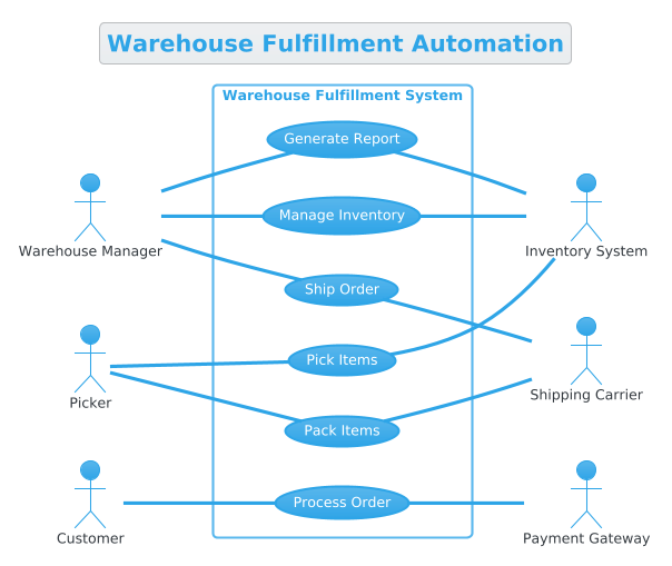
@startuml
    title Warehouse Fulfillment Automation
    /' This diagram outlines the functional requirements of a Warehouse Fulfillment Automation system, detailing interactions between operational staff, customers, and external systems. '/
    !theme cerulean
    left to right direction
    rectangle "Warehouse Fulfillment System" as WFS {
        usecase "Manage Inventory" as UC1
        usecase "Process Order" as UC2
        usecase "Pick Items" as UC3
        usecase "Pack Items" as UC4
        usecase "Ship Order" as UC5
        usecase "Generate Report" as UC6
    }

    actor "Warehouse Manager" as WM
    actor "Customer" as C
    actor "Picker" as P

    actor "Inventory System" as IS
    actor "Payment Gateway" as PG
    actor "Shipping Carrier" as SC

    WM -- UC1
    WM -- UC6
    WM -- UC5
    C -- UC2
    P -- UC3
    P -- UC4

    UC1 -- IS
    UC2 -- PG
    UC3 -- IS
    UC4 -- SC
    UC5 -- SC
    UC6 -- IS
@endumlStep-by-Step Architectural Walkthrough
Building a professional diagram requires a structured approach. We will construct this diagram in four distinct phases: Canvas Setup, System Boundary, Actors, and Associations.
Phase 1: Canvas Configuration & Layout Directives
Every PlantUML diagram starts with setup. We define the title, the visual theme, and the layout direction. For this use case diagram, a left-to-right flow is ideal as it naturally separates actors (left) from external systems (right).
title Warehouse Fulfillment Automation
/' This diagram outlines the functional requirements of a Warehouse Fulfillment Automation system, detailing interactions between operational staff, customers, and external systems. '/
!theme cerulean
left to right direction
Why this matters: The title tag ensures the diagram is self-documenting. The comment block (wrapped in /' ... '/) provides context for future readers without cluttering the visual output. The !theme cerulean directive applies a professional, clean color palette instantly.
Phase 2: Declaring Core Entities, Actors, and Boundaries
Next, we define the system boundary and the use cases contained within it. The rectangle command creates the boundary, and usecase commands define the functional goals inside it.
rectangle "Warehouse Fulfillment System" as WFS {
    usecase "Manage Inventory" as UC1
    usecase "Process Order" as UC2
    usecase "Pick Items" as UC3
    usecase "Pack Items" as UC4
    usecase "Ship Order" as UC5
    usecase "Generate Report" as UC6
}
Architectural Insight: By assigning IDs (like UC1, UC2), we make it easier to reference these use cases later when defining relationships. This keeps the code modular and readable.
Phase 3: Mapping Data Flows & Key Interactions
Now we introduce the actors. We split them into Primary Actors (internal roles) and Secondary Actors (external systems). This separation helps stakeholders understand who initiates actions versus who supports them.
actor "Warehouse Manager" as WM
actor "Customer" as C
actor "Picker" as P

actor "Inventory System" as IS
actor "Payment Gateway" as PG
actor "Shipping Carrier" as SC
Once defined, we map the interactions using the -- syntax. Crucially, we avoid arrowheads for standard associations to keep the diagram clean and focused on relationships rather than data flow direction.
WM -- UC1
WM -- UC6
C -- UC2
P -- UC3
UC1 -- IS
Phase 4: Grouping, Annotations & Visual Polish
The final step involves ensuring all connections are logical and the diagram is complete. We connect the secondary actors to the specific use cases they support. For example, “Process Order” connects to the “Payment Gateway”, and “Pick Items” connects to the “Inventory System”.
This phase ensures that the diagram accurately reflects the real-world dependencies of the warehouse automation system.
Syntax & Keyword Deep Dive
To master this diagram, you must understand the specific PlantUML keywords used. Here is a breakdown of the critical syntax elements:
title: Sets the main heading of the diagram. Essential for documentation clarity./' ... '/: The comment syntax. Text inside is rendered as a description in the diagram but is ignored by the compiler for layout logic.!theme: A directive to load a specific visual theme.ceruleanprovides a modern blue-tinted look suitable for enterprise software.left to right direction: A layout directive that forces the graph engine to render nodes horizontally from left to right, rather than the default top-to-bottom.rectangle ... as ... { ... }: Defines a system boundary (partition). Theaskeyword assigns an ID for referencing, and the curly braces contain the internal use cases.actor ... as ...: Declares a participant. Theaskeyword creates a shorthand ID (e.g.,WM) for the full name.usecase ... as ...: Declares a functional goal. Again, theaskeyword creates an ID for easy association.--: The association operator. In this diagram, we use it without arrowheads to denote a general relationship between an actor and a use case.
Best Practices & Pitfalls to Avoid
When creating Use Case Diagrams with PlantUML, follow these architectural guidelines to ensure maintainability and clarity:
- Keep Boundaries Tight: Do not include implementation details (like “Database Update”) inside the use cases. Use cases should represent business value (“Process Order”), not technical steps.
- Consistent Naming: Use the
askeyword consistently for all actors and use cases. This prevents errors when defining associations and makes refactoring easier. - Separate Primary and Secondary Actors: Visually distinguish between human roles and external systems. In our diagram, human actors are on the left, and external systems are on the right.
- Avoid Over-Complexity: If a diagram becomes too crowded, consider splitting it into subsystems (e.g., one diagram for “Order Management” and another for “Inventory Management”).
Try It Yourself with VPasCode
Start Building Use Case Diagrams Faster with VPasCode
Define your system requirements and visualize actor interactions instantly in your browser with VPasCode, the free PlantUML editor for software architects.