


In the modern landscape of educational technology, Learning Management Systems (LMS) handle critical workflows that require rigorous accuracy and clear accountability. The process of grade submission is not merely a data entry task; it is a multi-stage governance workflow involving Lecturers, automated System validation, and Course Coordinators. When these processes are ambiguous, errors can propagate, leading to academic disputes and administrative bottlenecks.

Visual modeling is the solution to this complexity. By using an activity diagram, architects and educators can visualize the flow of control and data across different roles. However, traditional drag-and-drop tools often struggle with versioning, portability, and the precision required for complex logic like parallel processing and conditional approval loops.
This tutorial demonstrates how to leverage VPasCode, a free web-based diagram-as-code tool, to build a robust PlantUML activity diagram. We will construct a professional-grade Grade Submission Process model that captures swimlane responsibilities, conditional branching, and parallel system tasks, all without installing any local software.
Understanding the Model: Purpose, Scope & Problem Framing
Before diving into the syntax, it is crucial to understand the architectural abstraction we are building. This diagram is not just a picture; it is a specification of a business process.
Diagram Abstraction & Representation
An activity diagram in PlantUML models the dynamic behavior of a system. It answers the question: “What happens next?” In this specific model, we use swimlanes (vertical partitions) to assign ownership of each step. This ensures that the visual representation clearly distinguishes between human actions (Lecturer, Coordinator) and automated system responses (Validation, Database Operations).
Target Domain Scope & Scenario
The scope of this diagram covers the lifecycle of a grade entry from initiation to final publication. It intentionally excludes unrelated LMS features like attendance tracking or forum moderation to maintain focus. The workflow includes:
- Initiation: The Lecturer logs in and prepares grade data.
- Validation: The System checks for data integrity and duplicates.
- Parallel Processing: Saving data and notifying stakeholders happen simultaneously.
- Governance: The Course Coordinator approves or rejects the submission.
Key Takeaways & Educational Insights
By the end of this tutorial, you will understand how to:
- Structure complex workflows using vertical swimlanes for clarity.
- Implement decision points using
if-elselogic with distinct exit paths. - Model concurrent system actions using the
forkkeyword. - Apply professional themes to enhance the visual quality of your technical documentation.
Complete Diagram & Full Source Code
Below is the finished blueprint for the Grade Submission Process. You can view the rendered result immediately, and the code block below is interactive.
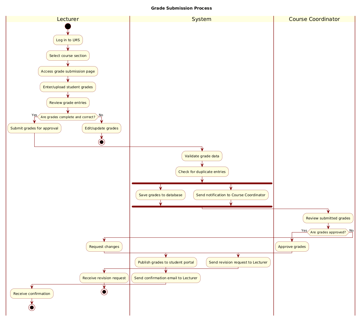
@startuml
!include https://static.visual-paradigm.com/web/resources/plantuml-stdlib/themes/rose.puml

title Grade Submission Process

|Lecturer|
start
:Log in to LMS;
:Select course section;
:Access grade submission page;
:Enter/upload student grades;
:Review grade entries;

if (Are grades complete and correct?) then (Yes)
  :Submit grades for approval;
else (No)
  :Edit/update grades;
  stop
endif

|System|
:Validate grade data;
:Check for duplicate entries;

fork
  :Save grades to database;
fork again
  :Send notification to Course Coordinator;
end fork

|Course Coordinator|
:Review submitted grades;

if (Are grades approved?) then (Yes)
  :Approve grades;
  |System|
  :Publish grades to student portal;
  :Send confirmation email to Lecturer;
  |Lecturer|
  :Receive confirmation;
  stop
else (No)
  :Request changes;
  |System|
  :Send revision request to Lecturer;
  |Lecturer|
  :Receive revision request;
  stop
endif

@endumlStep-by-Step Architectural Walkthrough
Building this diagram in VPasCode involves four distinct architectural phases. Follow these steps to replicate the logic and structure.
Phase 1: Canvas Configuration & Layout Directives
Every PlantUML diagram begins with boilerplate code that defines the environment. We start by declaring the root element and importing a visual theme to ensure the diagram looks professional immediately.
First, we initialize the diagram:
@startumlNext, we include the rose.puml theme. This is a standard library resource hosted by Visual Paradigm that provides a polished color palette and styling without manual CSS work:
!include https://static.visual-paradigm.com/web/resources/plantuml-stdlib/themes/rose.pumlFinally, we set the global title for the diagram to provide context:
title Grade Submission ProcessPhase 2: Declaring Core Entities, Actors, and Boundaries
The power of activity diagrams lies in swimlanes. These vertical lines define who is responsible for each action. We declare the Lecturer lane first, as they initiate the process.
|Lecturer|Inside this lane, we define the entry point using the start keyword. This creates the filled black circle that signifies the beginning of the flow:
startWe then map the sequential actions the Lecturer performs. In PlantUML, actions are represented by rounded rectangles. The colon : prefix indicates an action:
:Log in to LMS;
:Select course section;
:Access grade submission page;
:Enter/upload student grades;
:Review grade entries;
Phase 3: Mapping Data Flows & Key Interactions
Now we introduce logic. The Lecturer must verify their work before proceeding. This requires a conditional decision point using the if statement. The syntax follows the pattern if (condition) then (outcome).
if (Are grades complete and correct?) then (Yes)
  :Submit grades for approval;
else (No)
  :Edit/update grades;
  stop
endif
Notice the stop keyword in the else branch. This terminates the current flow path if the grades are incorrect, preventing invalid data from moving forward.
Next, we switch to the System lane to handle backend processing:
|System|
:Validate grade data;
:Check for duplicate entries;
Here, we utilize the fork construct to model parallel execution. The system performs two actions simultaneously: saving the data and notifying the coordinator.
fork
  :Save grades to database;
fork again
  :Send notification to Course Coordinator;
end fork
Phase 4: Grouping, Annotations & Visual Polish
The final phase involves the Course Coordinator lane, which acts as the governance checkpoint. This section mirrors the logic of the Lecturer but focuses on approval.
|Course Coordinator|
:Review submitted grades;

if (Are grades approved?) then (Yes)
  :Approve grades;
  |System|
  :Publish grades to student portal;
  :Send confirmation email to Lecturer;
  |Lecturer|
  :Receive confirmation;
  stop
else (No)
  :Request changes;
  |System|
  :Send revision request to Lecturer;
  |Lecturer|
  :Receive revision request;
  stop
endif
Observe how we switch back to the System and Lecturer lanes within the Coordinator’s block. This demonstrates how PlantUML allows dynamic lane transitions to show cross-role interactions clearly.
Syntax & Keyword Deep Dive
To master this notation, you must understand the specific PlantUML keywords used in this Grade Submission Process model.
start/stop: These define the lifecycle boundaries of the activity.startcreates the initial state, whilestopterminates a specific flow path (often used in error handling loops).|LaneName|: This syntax creates a swimlane. Any action defined below it belongs to that actor until a new lane is declared.if ... then ... else ... endif: This is the standard control structure for conditional logic. It splits the flow into two distinct paths based on a boolean condition.fork ... fork again ... end fork: This block indicates parallel processing. The actions inside are executed concurrently rather than sequentially, which is critical for modeling system tasks like saving data and sending emails.:Action;: The colon prefix denotes an activity node. The semicolon at the end terminates the line for PlantUML parsing.
Best Practices & Pitfalls to Avoid
When creating activity diagrams for educational or enterprise workflows, adhere to these architectural best practices to maintain clarity.
- Minimize Lane Switching: While PlantUML allows switching lanes dynamically, excessive jumping between swimlanes can confuse the reader. Try to group interactions by actor where possible.
- Define Clear Termination Points: Every flow path should eventually lead to a
stopnode or a final state. Avoid “orphaned” lines where the flow seems to end without a clear conclusion. - Use Descriptive Labels: In the
ifconditions, use clear questions (e.g., “Are grades complete?”) rather than abstract variables. This makes the diagram readable for non-technical stakeholders. - Keep Parallelism Meaningful: Use
forkonly when tasks truly happen simultaneously (like saving to DB and sending an email). If one task must finish before the next starts, use sequential arrows.
Try It Yourself with VPasCode
Start Building PlantUML Activity Diagrams Faster with VPasCode
Instantly prototype, edit, and visualize your educational workflows in your browser without installing any local tools or configuration.