


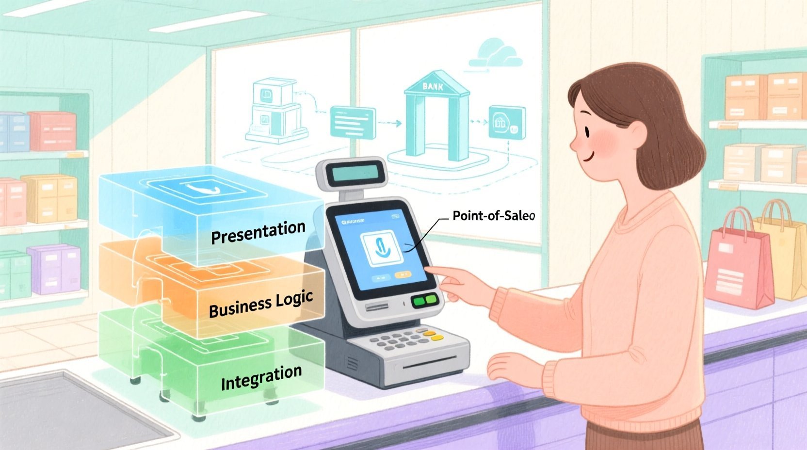
In the fast-paced retail industry, the Point-of-Sale (POS) terminal is the heartbeat of operations. It is not merely a cash register; it is a complex system integrating user interfaces, payment processing, inventory management, and external service communication. As retail systems scale, maintaining architectural clarity becomes critical. Poorly documented systems lead to integration errors, slow feature rollouts, and security vulnerabilities.
This is where diagram-as-code transforms the development lifecycle. By defining system architecture in code using PlantUML within VPasCode, software architects can ensure their documentation is versioned alongside the code, easily updated, and instantly rendered. This approach eliminates the ambiguity of hand-drawn sketches and provides a living blueprint that evolves with the software.
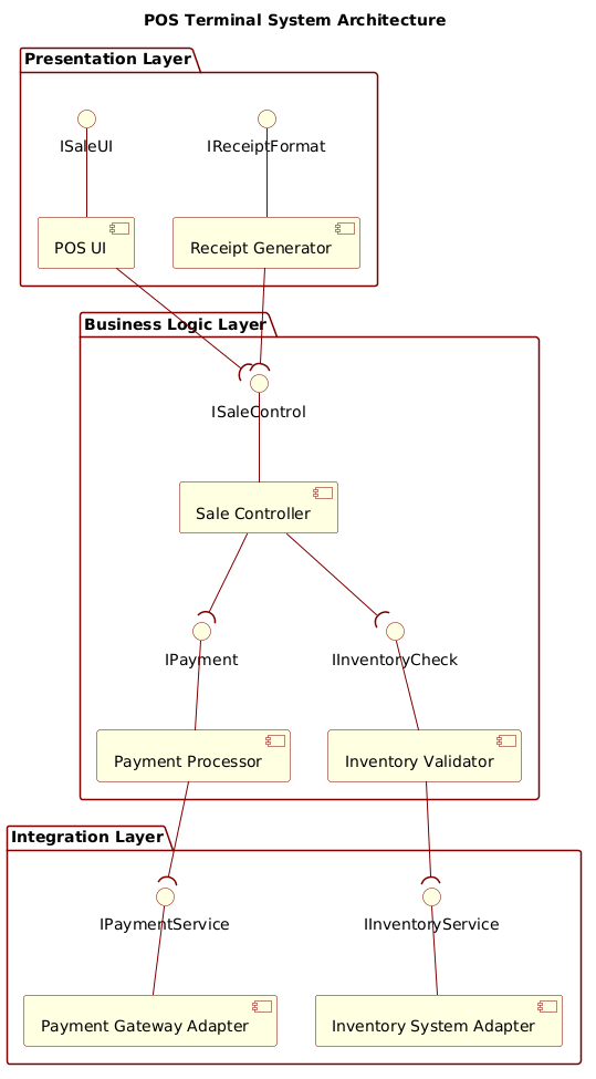
In this masterclass, we will construct a professional Component Diagram for a POS Terminal System. We will utilize the VPasCode web editor to visualize the separation of concerns across three architectural layers: Presentation, Business Logic, and Integration. By the end of this guide, you will understand how to model dependencies using provided and required interfaces, ensuring your architecture is modular, testable, and maintainable.
Understanding the Model: Purpose, Scope & Problem Framing
Diagram Abstraction & Representation
A Component Diagram is the ideal tool for modeling the high-level structure of a system. Unlike sequence diagrams that focus on runtime behavior, component diagrams focus on static structure and dependencies. In this specific model, we are abstracting the POS terminal into logical building blocks.
Components represent the deployable units of software (e.g., the UI, the Payment Processor). Interfaces define the contracts between these components. The diagram uses ball-and-socket notation to visualize how components connect. A socket (hole) represents a required interface (what the component needs), while a ball (provided interface) represents what a component offers. This visual distinction is crucial for understanding dependency directionality.
Target Domain Scope & Scenario
This diagram models the internal architecture of a POS Terminal System designed for a modern retail environment. The scope is strictly limited to the terminal application itself, excluding the physical hardware peripherals (like scanners or printers) and focusing instead on the software logic.
The architecture is divided into three distinct layers:
- Presentation Layer: Handles user interaction (touchscreen) and output (receipts).
- Business Logic Layer: Orchestrates the core workflows, such as calculating totals, validating stock, and initiating payments.
- Integration Layer: Acts as the bridge to external systems, such as bank payment gateways and central inventory databases.
By isolating these layers, the system ensures that changes in the UI do not break the payment logic, and changes in the external API do not disrupt the user experience.
Key Takeaways & Educational Insights
Through this exercise, you will gain insights into:
- Separation of Concerns: How to logically group components to manage complexity.
- Dependency Management: How to enforce dependencies through interfaces rather than direct coupling.
- Visual Clarity: How to use VPasCode to render complex relationships clearly for stakeholders.
Complete Diagram & Full Source Code
Below is the complete architecture for the POS Terminal System. This code is ready to be pasted directly into the VPasCode editor to render the diagram instantly.
@startuml
!include https://static.visual-paradigm.com/web/resources/plantuml-stdlib/themes/rose.puml

title POS Terminal System Architecture

/'
This component diagram illustrates the high-level architecture of a Point-of-Sale (POS) Terminal System.
The system is organized into three logical layers: Presentation, Business Logic, and Integration.
The Presentation layer handles user interaction and receipt formatting. The Business Logic layer
orchestrates core sales workflows, payment processing, and inventory validation. The Integration
layer manages communication with external services such as payment gateways and inventory systems.
Components interact through provided and required interfaces using ball-and-socket notation,
emphasizing clear separation of concerns and pluggable dependencies.
'/

package "Presentation Layer" {
    interface "ISaleUI" as ISaleUI
    interface "IReceiptFormat" as IReceiptFormat

    component "POS UI" as UI
    component "Receipt Generator" as Receipt

    ISaleUI -- UI
    IReceiptFormat -- Receipt
}

package "Business Logic Layer" {
    interface "ISaleControl" as ISaleControl
    interface "IPayment" as IPayment
    interface "IInventoryCheck" as IInventoryCheck

    component "Sale Controller" as SaleCtrl
    component "Payment Processor" as PaymentProc
    component "Inventory Validator" as InvValid

    ISaleControl -- SaleCtrl
    IPayment -- PaymentProc
    IInventoryCheck -- InvValid
}

package "Integration Layer" {
    interface "IPaymentService" as IPaymentService
    interface "IInventoryService" as IInventoryService

    component "Payment Gateway Adapter" as PmtAdapter
    component "Inventory System Adapter" as InvAdapter

    IPaymentService -- PmtAdapter
    IInventoryService -- InvAdapter
}

' Required interfaces (socket) from components - using ( on the right
UI --( ISaleControl
Receipt --( ISaleControl
SaleCtrl --( IInventoryCheck
SaleCtrl --( IPayment
PaymentProc --( IPaymentService
InvValid --( IInventoryService

@endumlStep-by-Step Architectural Walkthrough
Building this diagram in VPasCode is an iterative process. We will break down the construction into four distinct phases to ensure architectural integrity and visual clarity.
Phase 1: Canvas Configuration & Layout Directives
Before defining components, we must set the stage. This involves selecting a visual theme and defining the overall layout direction. In PlantUML, themes control the colors and styling of shapes, ensuring the diagram looks professional.
We begin by including the rose.puml theme, which provides a clean, modern aesthetic suitable for enterprise architecture. We also explicitly set the direction to left-to-right, which is standard for reading flow in Western languages.
!include https://static.visual-paradigm.com/web/resources/plantuml-stdlib/themes/rose.puml

title POS Terminal System Architecture
Additionally, we add a comment block using /' and '/ to describe the diagram’s context. This documentation is embedded directly in the code, ensuring that anyone viewing the source understands the problem space immediately.
Phase 2: Declaring Core Entities, Actors, and Boundaries
Next, we define the structural boundaries of the system using package directives. In component modeling, packages act as logical containers that group related components. This mirrors the layered architecture we defined earlier.
We create three packages: Presentation Layer, Business Logic Layer, and Integration Layer. Inside each package, we declare the components and interfaces they contain.
package "Business Logic Layer" {
    interface "ISaleControl" as ISaleControl
    component "Sale Controller" as SaleCtrl

    ISaleControl -- SaleCtrl
}
Note that we define the interface ISaleControl first, then the component SaleCtrl, and finally link them. This establishes that the component provides the interface.
Phase 3: Mapping Data Flows & Key Interactions
Once the components are defined within their layers, we must define how they interact. In PlantUML, interaction is defined using association lines. We have two types of connections in this diagram: Provided Interfaces and Required Interfaces.
A Provided Interface is denoted by a solid line with a ball on the providing side. For example, the Sale Controller provides control logic. A Required Interface is denoted by a line with a socket (a small circle or parenthesis) on the consuming side. This indicates that the component needs a service to function.
UI --( ISaleControlIn the snippet above, the UI component requires the ISaleControl interface. The --( syntax is critical. It tells VPasCode to render a socket on the right side of the UI component, visually indicating a dependency.
Phase 4: Grouping, Annotations & Visual Polish
The final phase ensures the diagram is readable and consistent. We verify that all layers are properly nested within their packages. We ensure that interface names follow a consistent naming convention (e.g., I prefix for interfaces).
We also review the connections to ensure there are no circular dependencies that could cause runtime errors. For instance, the Integration Layer should only be consumed by the Business Logic Layer, never the other way around. This strict layering is enforced by the direction of our interface connections.
Syntax & Keyword Deep Dive
To replicate this architecture or build your own, you must understand the specific PlantUML syntax features used in this diagram.
package: Used to group components logically. In this diagram, it represents architectural layers. Syntax:package "Name" { ... }.component: Defines a software component. Syntax:component "Label" as Alias.interface: Defines a contract. Syntax:interface "Label" as Alias.--: Represents a general association or provided interface. Syntax:Interface -- Component.--(: Represents a required interface (socket). The parenthesis(creates the socket on the right side. Syntax:Component --( Interface./' ... '/: Used for multi-line comments that describe the diagram context without affecting the rendering.
Best Practices & Pitfalls to Avoid
When building component diagrams with VPasCode, adhere to these best practices to maintain high-quality architecture documentation.
- Consistent Naming Conventions: Always prefix interfaces with
I(e.g.,ISaleUI). This immediately distinguishes contracts from implementations in the visual model. - Minimize Cross-Layer Dependencies: Ensure components in the
Presentation Layerdo not directly connect to theIntegration Layer. Always route through theBusiness Logic Layer. This maintains the separation of concerns. - Use Descriptive Labels: While aliases like
SaleCtrlare useful for code, the display label"Sale Controller"is more readable for stakeholders. Always use quoted strings for labels. - Keep Diagrams Modular: If the system grows, consider splitting this diagram into multiple files (e.g., one for UI, one for Backend) and including them. VPasCode supports complex includes, allowing you to scale without cluttering a single file.
Try It Yourself with VPasCode
Start Building POS System Diagrams Faster with VPasCode
Instantly prototype, test, and customize your architecture diagrams online in VPasCode without installing any tools or configuring local environments.