


In the complex landscape of pension fund management, visualizing financial workflows is critical for compliance, system architecture, and stakeholder communication. The annuity payout process represents one of the most sensitive operational flows in any pension system, involving multiple actors, conditional logic, parallel processing, and strict audit trail requirements.

For software architects and financial system designers, creating accurate activity diagrams helps identify bottlenecks, ensure regulatory compliance, and validate system boundaries before implementation begins. Diagramming-as-code with PlantUML in VPasCode transforms this modeling process from time-consuming manual drawing into rapid, versionable, and reusable technical documentation.
This tutorial demonstrates how to construct a professional annuity payout activity diagram that captures real-world financial workflows including eligibility validation, parallel payment processing, tax calculations, and multi-party communication patterns.
Understanding the Model: Purpose, Scope & Problem Framing
Diagram Abstraction & Representation
An activity diagram in PlantUML models the dynamic behavior of a system by showing the flow of control from one activity to another. In the context of financial systems, activity diagrams are particularly valuable because they:
- Visualize Decision Points: Show conditional branches like eligibility checks and tax applicability
- Map Parallel Processing: Illustrate concurrent operations like payment schedule generation and fund transfer initiation
- Define Actor Boundaries: Use swimlanes to clearly separate responsibilities between pensioners, system components, and banking interfaces
- Track State Transitions: Document the complete lifecycle from payout request to final confirmation
Target Domain Scope & Scenario
This diagram specifically models the annuity payout workflow within a Pension Fund System, covering:
- Input Scope: Pensioner-initiated payout requests
- Processing Boundaries: Eligibility validation, account calculations, payment scheduling, and fund transfers
- Output Scope: Monthly annuity payment delivery and transaction ledger updates
- Excluded Dependencies: External banking infrastructure details and tax authority communication protocols
Key Takeaways & Educational Insights
By completing this tutorial, you will gain:
- Understanding of swimlane architecture for multi-party financial workflows
- Proficiency with PlantUML conditional and fork-join syntax
- Best practices for modeling parallel processing in activity diagrams
- Knowledge of how to structure diagrams for regulatory audit trails
Complete Diagram & Full Source Code
Below is the finished annuity payout activity diagram, rendered in VPasCode’s browser-based editor. Study the swimlane structure, conditional branches, and parallel processing patterns before examining the step-by-step construction walkthrough.
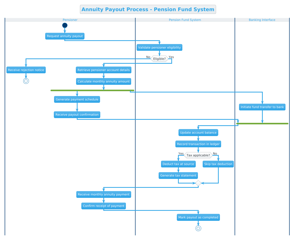
@startuml
!theme cerulean
title Annuity Payout Process - Pension Fund System

|Pensioner|
start
:Request annuity payout;

|Pension Fund System|
:Validate pensioner eligibility;

if (Eligible?) then (No)
  |Pensioner|
  :Receive rejection notice;
  stop
else (Yes)
  :Retrieve pensioner account details;
  :Calculate monthly annuity amount;
  fork
    :Generate payment schedule;
    |Pensioner|
    :Receive payout confirmation;
  fork again
    |Banking Interface|
    :Initiate fund transfer to bank;
  end fork
  |Pension Fund System|
  :Update account balance;
  :Record transaction in ledger;
  if (Tax applicable?) then (Yes)
    :Deduct tax at source;
    :Generate tax statement;
  else (No)
    :Skip tax deduction;
  endif
  |Pensioner|
  :Receive monthly annuity payment;
  :Confirm receipt of payment;
  |Pension Fund System|
  :Mark payout as completed;
  stop
endif
@endumlStep-by-Step Architectural Walkthrough
Phase 1: Canvas Configuration & Layout Directives
Every PlantUML activity diagram begins with proper canvas setup. This phase establishes the visual theme, diagram title, and overall styling that will apply to all subsequent elements.
@startuml
!theme cerulean
title Annuity Payout Process - Pension Fund System
The @startuml directive marks the beginning of the diagram. The !theme cerulean directive applies a professional blue color scheme optimized for financial documentation. The title directive provides a clear, searchable heading that appears at the diagram’s top.
Phase 2: Declaring Core Entities, Actors, and Boundaries
Swimlanes define responsibility boundaries in activity diagrams. Each swimlane represents a distinct actor or system component that performs specific actions within the workflow.
|Pensioner|
start
:Request annuity payout;

|Pension Fund System|
:Validate pensioner eligibility;
The |Actor Name| syntax creates horizontal swimlanes. The start node marks the diagram’s entry point, while activity nodes (enclosed in colons) represent discrete operations. Notice how the Pensioner initiates the process, then control transfers to the Pension Fund System for validation.
Phase 3: Mapping Data Flows & Key Interactions
This phase implements conditional logic and parallel processing, which are critical for accurate financial workflow modeling.
if (Eligible?) then (No)
  |Pensioner|
  :Receive rejection notice;
  stop
else (Yes)
  :Retrieve pensioner account details;
  :Calculate monthly annuity amount;
The if (condition) then (branch1) else (branch2) syntax creates decision diamonds with labeled paths. The stop node terminates the diagram when eligibility fails. Within the else branch, parallel processing begins with the fork directive.
  fork
    :Generate payment schedule;
    |Pensioner|
    :Receive payout confirmation;
  fork again
    |Banking Interface|
    :Initiate fund transfer to bank;
  end fork
The fork and fork again directives create parallel execution paths that converge at end fork. This accurately represents real-world scenarios where payment scheduling and fund transfers occur simultaneously rather than sequentially.
Phase 4: Grouping, Annotations & Visual Polish
The final phase completes the workflow with tax handling logic and final state transitions.
  if (Tax applicable?) then (Yes)
    :Deduct tax at source;
    :Generate tax statement;
  else (No)
    :Skip tax deduction;
  endif
  |Pensioner|
  :Receive monthly annuity payment;
  :Confirm receipt of payment;
  |Pension Fund System|
  :Mark payout as completed;
  stop
The second conditional handles tax compliance requirements, a critical consideration for financial systems. The final stop node marks successful workflow completion, providing a clear end state for audit and monitoring purposes.
Syntax & Keyword Deep Dive
Understanding PlantUML’s activity diagram syntax is essential for creating maintainable, accurate models. Here are the key keywords used in this diagram:
@startuml: Declares the start of a PlantUML activity diagram block|Swimlane Name|: Creates a horizontal swimlane to group activities by actor or system componentstart: Marks the entry point of the activity flowstop: Marks the termination point of the activity flow:Activity Name;: Defines an activity node (operation or process step)if (condition) then (branch) else (branch): Creates conditional branching with labeled pathsfork / fork again / end fork: Defines parallel execution paths that converge!theme cerulean: Applies a predefined color theme to the diagramtitle: Sets the diagram’s title for documentation and searchability
Best Practices & Pitfalls to Avoid
When modeling financial workflows with PlantUML activity diagrams, follow these best practices to ensure clarity and maintainability:
- Keep Swimlanes Meaningful: Each swimlane should represent a distinct responsibility boundary. Avoid creating swimlanes that contain only one or two activities, as this dilutes the visual separation of concerns.
- Label Conditional Branches: Always label both the
thenandelsepaths clearly. Financial audits require unambiguous understanding of all decision outcomes. - Limit Fork Complexity: Keep parallel processing paths to two or three branches maximum. Excessive parallelism makes diagrams difficult to read and maintain.
- Use Consistent Naming Conventions: Activity names should follow a verb-noun pattern (e.g., “Validate eligibility” rather than “Eligibility validation”) for clarity.
- Document End States: Every activity diagram should have clear start and stop nodes. This enables automated validation and audit trail generation.
Start Building PlantUML Activity Diagrams Faster with VPasCode
Test, preview, and customize this annuity payout diagram instantly in your browser with VPasCode’s free PlantUML editor—no installation required.