


In the fast-paced domain of financial technology, clarity in system requirements is paramount. When designing an Automated Teller Machine (ATM) system, stakeholders must agree on how users interact with the core banking infrastructure. A well-structured Use Case Diagram serves as the blueprint for these interactions, mapping out the functional goals of the system against the roles that access it.
Building this model using diagram-as-code with PlantUML within VPasCode offers significant advantages over traditional drag-and-drop tools. It allows software architects and developers to maintain a living documentation repository where changes to logic are instantly reflected in the visual output. By leveraging VPasCode, you can prototype complex banking workflows in the browser without installing Java or configuring local dependencies.
Understanding the Model: Purpose, Scope & Problem Framing
Before diving into the syntax, it is essential to understand the abstraction being modeled.
Diagram Abstraction & Representation
A Use Case Diagram models the functional requirements of a system from the perspective of external users. In this context, actors represent the entities (people or systems) initiating actions, while use cases represent the specific services or goals the system provides (e.g., “Withdraw Cash”). The diagram defines the boundary of the system, distinguishing between internal processing and external interaction.
Target Domain Scope & Scenario
This tutorial focuses on a standard ATM System within the finance industry. The scope includes the primary user (Customer) and a secondary support role (Bank Clerk). It covers critical financial transactions such as withdrawals, deposits, transfers, and authentication. It excludes backend database details or network protocols, focusing strictly on the user-system interface.
Key Takeaways & Educational Insights
By constructing this model, you will gain insights into system boundaries, actor responsibilities, and the hierarchy of operations. You will learn how to distinguish between mandatory flows (include) and optional extensions (extend), ensuring the diagram accurately reflects real-world banking logic.
Complete Diagram & Full Source Code
Below is the finalized blueprint for the ATM System Use Case Diagram. You can visualize the result immediately after reviewing the code.
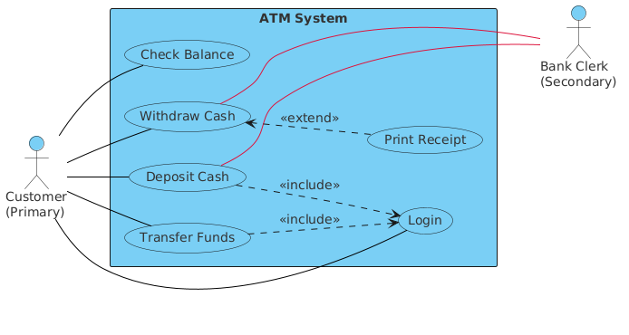
Here is the complete source code to generate this diagram.
@startuml
!include https://static.visual-paradigm.com/web/resources/plantuml-stdlib/themes/vp.puml
skinparam defaultFontSize 14
skinparam defaultFontColor #333333
skinparam vpDiagramType UseCaseDiagram

left to right direction
actor "Customer\n(Primary)" as cust
actor "Bank Clerk\n(Secondary)" as clerk

rectangle "ATM System" {
  usecase "Withdraw Cash" as UC1
  usecase "Deposit Cash" as UC2
  usecase "Transfer Funds" as UC3
  usecase "Check Balance" as UC4
  usecase "Print Receipt" as UC5
  usecase "Login" as UC6
}

cust -[#black]- UC1
cust -[#black]- UC2
cust -[#black]- UC3
cust -[#black]- UC4
cust -[#black]- UC6
UC1 --[#crimson]- clerk
UC2 --[#crimson]- clerk
UC2 ..> UC6 : <<include>>
UC3 ..> UC6 : <<include>>
UC1 <.. UC5 : <<extend>>
@endumlStep-by-Step Architectural Walkthrough
Follow this chronological guide to build the diagram from scratch using the VPasCode web editor.
Phase 1: Canvas Configuration & Layout Directives
Start by setting the environment. We need to include the VPasCode theme to ensure the diagram matches the platform’s visual standards. We also define the layout direction to optimize horizontal space for wide banking workflows.
!include https://static.visual-paradigm.com/web/resources/plantuml-stdlib/themes/vp.puml
skinparam defaultFontSize 14
skinparam defaultFontColor #333333
skinparam vpDiagramType UseCaseDiagram

left to right direction
Phase 2: Declaring Core Entities, Actors, and Boundaries
Define the actors representing the human roles and the system boundary rectangle. The system rectangle encapsulates all internal functions, separating them from external actors.
actor "Customer
(Primary)" as cust
actor "Bank Clerk
(Secondary)" as clerk

rectangle "ATM System" {
  usecase "Withdraw Cash" as UC1
  usecase "Deposit Cash" as UC2
  usecase "Transfer Funds" as UC3
  usecase "Check Balance" as UC4
  usecase "Print Receipt" as UC5
  usecase "Login" as UC6
}
Phase 3: Mapping Data Flows & Key Interactions
Connect the actors to the use cases using association lines. Notice the solid lines for primary interactions and the colored lines for specific relationships with the clerk.
cust -[#black]- UC1
cust -[#black]- UC2
cust -[#black]- UC3
cust -[#black]- UC4
cust -[#black]- UC6
UC1 --[#crimson]- clerk
UC2 --[#crimson]- clerk
Phase 4: Grouping, Annotations & Visual Polish
Finally, define the complex logical relationships using stereotypes like <<include>> and <<extend>>. These arrows indicate that certain actions are mandatory prerequisites or optional enhancements.
UC2 ..> UC6 : <<include>>
UC3 ..> UC6 : <<include>>
UC1 <.. UC5 : <<extend>>
Syntax & Keyword Deep Dive
Understanding the specific PlantUML syntax used in this diagram is crucial for adapting it to other projects.
!include: Imports external resources, such as the VPasCode theme library, to standardize styling across diagrams.skinparam: Sets global visual properties like font size, color, and diagram type to ensure consistency.actor: Declares a participant in the system. Labels can be multi-line using the \n character for clarity.rectangle: Defines the system boundary. All use cases inside this block are considered internal to the system.usecase: Defines a specific functional goal or service provided by the system.-[#color]-: Creates a solid association line with a specific color (e.g., black for primary users)...><<include>>: Indicates a mandatory dependency. For example, “Deposit Cash” includes “Login”.<..<<extend>>: Indicates an optional behavior. For example, “Withdraw Cash” extends to “Print Receipt”.
Best Practices & Pitfalls to Avoid
To maintain high-quality architectural documentation, follow these guidelines:
- Keep Boundaries Clear: Ensure only system functions are inside the
rectangle. Actors should always remain outside. - Use Meaningful Labels: Avoid generic names like “Action 1”. Use descriptive verbs like “Withdraw Cash” to improve readability.
- Limit Relationships: Do not overcrowd the diagram. If a use case has too many dependencies, consider breaking it into sub-processes.
- Consistent Styling: Use
skinparamdirectives to enforce a consistent look, especially when collaborating with other architects.
Try It Yourself with VPasCode
Start Building ATM Use Case Diagrams Faster with VPasCode
Instantly prototype and customize this banking workflow diagram online in VPasCode without installing any tools or configuring environments.