


In the high-stakes world of digital entertainment, the seamless delivery of video content is paramount. For streaming media platforms, the difference between a satisfied subscriber and a frustrated churn risk often lies in the invisible mechanics of buffering. When a user clicks play, a complex dance of data requests, network latency checks, and local storage management occurs in milliseconds. Architecting this flow requires more than just backend code; it demands a clear visual representation of the state transitions and decision logic that govern the playback experience.
Diagramming-as-code with PlantUML offers a unique advantage for software architects and engineers in the entertainment industry. Unlike static drawing tools, PlantUML allows teams to define the logic of the system in text, version the diagram alongside their source code, and render it instantly. Using VPasCode, the free web-based diagram-as-code editor, teams can prototype these complex interactions without installing local dependencies. This approach ensures that the documentation evolves in lockstep with the implementation, providing a living blueprint for how video segments are fetched, buffered, and played back.

Understanding the Model: Purpose, Scope & Problem Framing
Before diving into the syntax, it is crucial to understand why an activity diagram is the appropriate abstraction for this scenario. In the context of streaming media, an activity diagram models the dynamic behavior of the system over time. It captures the flow of control from the initial user action (clicking play) through the network interactions and into the final state (stream completion or buffering stall).
Diagram Abstraction & Representation
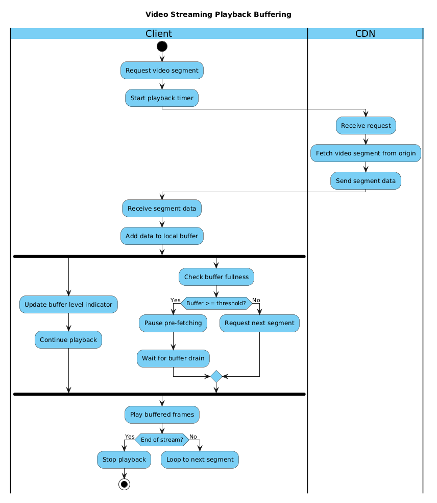
This specific model utilizes swimlanes to separate concerns between the Client (the user’s device or application) and the CDN (Content Delivery Network). This separation is critical because it highlights the boundary between local logic (buffer management, playback timing) and remote logic (segment fetching, origin server communication). The diagram illustrates how the client initiates a request, waits for data, and then manages the local buffer state concurrently with the playback process.
Target Domain Scope & Scenario
The scope of this model covers the core playback loop. It intentionally excludes complex features like adaptive bitrate switching (ABR) logic or authentication handshakes to focus on the fundamental buffering mechanism. The scenario assumes a standard HTTP-based streaming protocol where video content is broken into segments. The diagram models the decision-making process: should we keep downloading more data (prefetching), or should we pause to let the buffer drain? This is the core logic that prevents video stuttering.
Key Takeaways & Educational Insights
By studying and constructing this diagram, readers will gain insights into modeling parallel processes using the fork keyword, handling conditional logic with if-else statements, and managing state transitions with start and stop nodes. It demonstrates how to represent a continuous loop of operations that terminates only when a specific condition (End of Stream) is met.
Complete Diagram & Full Source Code
Below is the finished blueprint for the Video Streaming Playback Buffering process. This diagram utilizes the VP theme for a professional look and includes swimlanes to clearly delineate responsibilities between the client and the network.
@startuml
!include https://static.visual-paradigm.com/web/resources/plantuml-stdlib/themes/vp.puml

title Video Streaming Playback Buffering

|Client|
start
:Request video segment;
:Start playback timer;

|CDN|
:Receive request;
:Fetch video segment from origin;
:Send segment data;

|Client|
:Receive segment data;
:Add data to local buffer;

fork
  :Update buffer level indicator;
  :Continue playback;
fork again
  :Check buffer fullness;
  if (Buffer >= threshold?) then (Yes)
    :Pause pre-fetching;
    :Wait for buffer drain;
  else (No)
    :Request next segment;
  endif
end fork

:Play buffered frames;

if (End of stream?) then (Yes)
  :Stop playback;
  stop
else (No)
  :Loop to next segment;
  detach
endif

@endumlStep-by-Step Architectural Walkthrough
Building this diagram in VPasCode is a structured process. We will break down the construction into four logical phases, moving from the global canvas configuration to the specific logic flows within the swimlanes.
Phase 1: Canvas Configuration & Layout Directives
Every PlantUML diagram begins with the preamble. In this section, we define the theme and the title. Using the VP theme ensures the diagram matches the Visual Paradigm aesthetic, making it suitable for professional documentation.
We start by declaring the diagram type and including the theme file:
@startuml
!include https://static.visual-paradigm.com/web/resources/plantuml-stdlib/themes/vp.puml
Next, we set the title directive. This is not just a label; it provides context for anyone viewing the rendered output, ensuring the diagram is self-documenting. We place this immediately after the theme include to ensure it is recognized as the main header.
title Video Streaming Playback BufferingPhase 2: Declaring Core Entities, Actors, and Boundaries
The foundation of a clear activity diagram is the swimlane structure. Swimlanes organize the diagram spatially, assigning specific activities to specific actors. In our streaming scenario, we have two distinct actors: the Client and the CDN.
We define the first swimlane for the Client:
|Client|Inside this lane, we define the entry point using the start node. This marks the beginning of the activity flow. We then list the initial actions taken by the client application upon receiving a play command.
start
:Request video segment;
:Start playback timer;
Next, we define the CDN swimlane. This represents the network infrastructure. Activities here are triggered by the client’s request but occur on a remote server.
|CDN|
:Receive request;
:Fetch video segment from origin;
:Send segment data;
Finally, we return to the Client swimlane to handle the response. The client receives the data and manages its local storage.
|Client|
:Receive segment data;
:Add data to local buffer;
Phase 3: Mapping Data Flows & Key Interactions
This is the most complex part of the diagram: handling concurrency and decision logic. Streaming is not a linear process; the device must play video while simultaneously ensuring the buffer remains full. We use the fork keyword to model this parallel execution.
We initiate the fork to split the flow into two concurrent paths:
fork
  :Update buffer level indicator;
  :Continue playback;
The first branch represents the user experience path (playing video). The second branch, defined by fork again, represents the maintenance path (checking buffer levels). This parallel structure is critical because it shows that the user can watch video while the system decides whether to fetch more data.
Inside the second branch, we implement conditional logic using if and else. This models the buffering threshold strategy.
fork again
  :Check buffer fullness;
  if (Buffer >= threshold?) then (Yes)
    :Pause pre-fetching;
    :Wait for buffer drain;
  else (No)
    :Request next segment;
  endif
end fork
If the buffer is full (Yes), we pause fetching to save bandwidth. If it is low (No), we request the next segment. This logic directly maps to the optimization strategies used in modern streaming players.
Phase 4: Grouping, Annotations & Visual Polish
The final phase involves closing the loop and handling the termination state. After the fork, we have a Play buffered frames step. Following this, we need to determine if the entire video has finished.
We use a final conditional check for the End of stream condition. If true, we transition to the stop node. If false, we loop back. The detach keyword is used here to indicate that the flow continues without necessarily joining the previous fork synchronization point, allowing the loop to restart the segment request process efficiently.
if (End of stream?) then (Yes)
  :Stop playback;
  stop
else (No)
  :Loop to next segment;
  detach
endif
Syntax & Keyword Deep Dive
To fully master this diagram, it is essential to understand the specific PlantUML keywords used. These syntax elements control the rendering and logic flow.
title: Defines the main heading of the diagram. It appears at the top of the rendered output and is essential for documentation clarity.|Actor|: Defines a swimlane. The text inside the pipes represents the participant (e.g., Client, CDN). Activities following this declaration belong to that swimlane.start/stop: These nodes mark the entry and exit points of the activity flow. They are rendered as solid black circles.fork/fork again/end fork: These keywords create parallel branches of execution.forkstarts the split,fork againadds a new branch to the split, andend forkmerges them back together.if (Condition) then (Label) else (Label) endif: This syntax creates a diamond-shaped decision node. The labels (Yes/No) appear on the outgoing arrows, guiding the viewer through the logic paths.detach: Used to indicate that the flow continues without synchronizing with the fork. This is common in loops where the next iteration does not need to wait for the previous parallel branch to finish.:Action;: The colon syntax is the standard way to define an activity node. The text inside the colon is the description of the action.
Best Practices & Pitfalls to Avoid
When modeling streaming logic or similar complex workflows, adherence to best practices ensures the diagram remains maintainable and readable.
- Maintain Swimlane Clarity: Do not mix responsibilities across swimlanes. If a Client action requires a CDN response, the flow should cross the lane boundary, but the action itself should remain in the correct swimlane. This prevents confusion about who is responsible for which step.
- Limit Fork Depth: While PlantUML supports multiple forks, too many parallel branches can make the diagram visually cluttered. In this streaming example, we limit it to two branches (Playback vs. Buffering). If you need more, consider splitting the diagram into sub-activities.
- Use Meaningful Labels: Avoid generic labels like “Process Data.” Instead, use specific terms like “Fetch video segment from origin.” This makes the diagram self-documenting for future engineers.
- Check Threshold Logic: When modeling buffering, ensure the logic accounts for edge cases. For example, what happens if the network fails? While this diagram focuses on the happy path, a robust production model might include error handling swimlanes or timeout states.
Start Building Streaming Logic Diagrams Faster with VPasCode
Design complex video buffering flows instantly in your browser with VPasCode, the free PlantUML editor for software architects.