


Introduction: Architecting Retail Transaction Flows
In the fast-paced environment of modern retail, the Point-of-Sale (POS) terminal serves as the critical nexus between customer interaction, inventory management, and financial processing. For software architects and business analysts, clearly defining the functional boundaries of a POS system is essential before a single line of backend code is written. A well-structured Use Case diagram provides this clarity by abstracting complex system behaviors into understandable functional goals and actor interactions.

Using a diagram-as-code approach with PlantUML within the VPasCode editor allows teams to treat system modeling as a living documentation asset. Unlike static image tools, text-based modeling enables rapid iteration, versioning of thoughts (via external tools), and instant visual feedback. In this masterclass, we will build a comprehensive Use Case diagram for a POS Terminal, demonstrating how to structure system boundaries, distinguish between primary and secondary actors, and model external dependencies like payment gateways.
Understanding the Model: Purpose, Scope & Problem Framing
Before diving into the syntax, it is crucial to understand the abstraction we are creating. A Use Case diagram answers the question: “What does the system do for its users?” rather than “How does the system work internally?”.
Diagram Abstraction & Representation
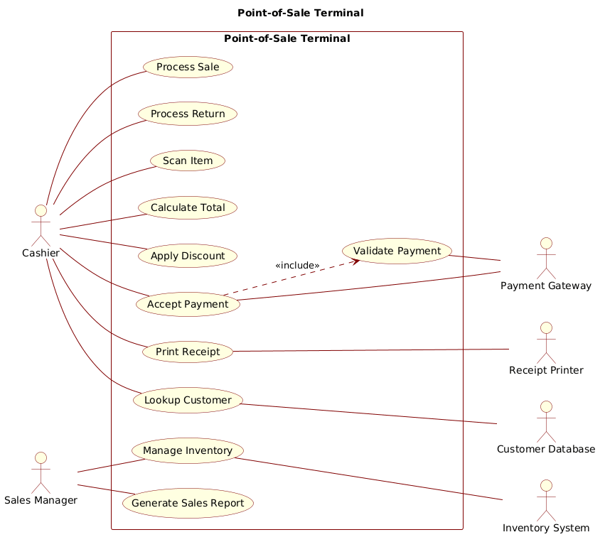
This diagram models the functional requirements of the POS system. It focuses on the interactions between human actors (store staff) and the system itself. The actor represents a role (e.g., Cashier) that interacts with the system to achieve a goal. The use case represents a specific functional unit of work (e.g., Process Sale). By separating these elements, we ensure that the requirements are decoupled from the implementation details.
Target Domain Scope & Scenario
The scope of this model is the Point-of-Sale Terminal software interface. It intentionally excludes the internal database schema or the physical hardware wiring, focusing instead on the logical transactions. We define the system boundary as the “Point-of-Sale Terminal” rectangle. Inside, we model the core retail functions. Outside, we model the external systems required to complete those functions, such as the Payment Gateway or Inventory System. This distinction helps developers understand API integration points early in the design phase.
Key Takeaways & Educational Insights
By completing this tutorial, you will gain the ability to:
- Define clear system boundaries to separate internal logic from external dependencies.
- Distinguish between primary actors (direct users) and secondary actors (supporting systems).
- Apply PlantUML syntax for relationships, including includes and associations without arrowheads for standard use cases.
- Utilize the VPasCode editor for instant rendering and theme customization.
Complete Diagram & Full Source Code
Below is the finished blueprint for the Point-of-Sale Terminal Use Case diagram. This model demonstrates a clean separation of concerns, with primary actors on the left and secondary system integrations on the right.
@startuml
!include https://static.visual-paradigm.com/web/resources/plantuml-stdlib/themes/rose.puml

title Point-of-Sale Terminal

/'
  This diagram models the primary functions of a Point-of-Sale (POS) terminal
  used in a retail environment. The system handles sales transactions, returns,
  payment processing, and customer management. Primary actors are store staff
  who initiate operations, while secondary actors represent external systems
  and services that the POS interacts with to complete tasks.
'/

left to right direction

rectangle "Point-of-Sale Terminal" {
  usecase "Process Sale" as UC1
  usecase "Process Return" as UC2
  usecase "Scan Item" as UC3
  usecase "Calculate Total" as UC4
  usecase "Apply Discount" as UC5
  usecase "Accept Payment" as UC6
  usecase "Print Receipt" as UC7
  usecase "Lookup Customer" as UC8
  usecase "Manage Inventory" as UC9
  usecase "Generate Sales Report" as UC10
  usecase "Validate Payment" as UC11
}

' Primary actors (left side)
actor "Cashier" as Cashier
actor "Sales Manager" as Manager

Cashier -- UC1
Cashier -- UC2
Cashier -- UC3
Cashier -- UC4
Cashier -- UC5
Cashier -- UC6
Cashier -- UC7
Cashier -- UC8

Manager -- UC9
Manager -- UC10

' Secondary actors (right side)
actor "Payment Gateway" as PaymentGateway
actor "Inventory System" as InventorySystem
actor "Customer Database" as CustomerDB
actor "Receipt Printer" as Printer

UC6 --- PaymentGateway
UC9 --- InventorySystem
UC8 --- CustomerDB
UC7 --- Printer

' Included use case relationship
UC6 ..> UC11 : <<include>>
UC11 -- PaymentGateway

@endumlStep-by-Step Architectural Walkthrough
Let’s deconstruct the code into four logical phases to understand how the visual model is constructed.
Phase 1: Canvas Configuration & Layout Directives
The foundation of any PlantUML diagram begins with the preamble. We include the rose.puml theme to ensure a consistent, professional visual style without manual CSS adjustments. We also set the layout direction to left to right, which aligns with standard reading patterns and helps separate actors from the system boundary clearly.
!include https://static.visual-paradigm.com/web/resources/plantuml-stdlib/themes/rose.puml
left to right direction
Phase 2: Declaring Core Entities, Actors, and Boundaries
We define the system boundary using the rectangle keyword. This visually encapsulates the internal logic of the POS terminal. Inside this boundary, we declare the use cases. Using aliases (e.g., as UC1) keeps the code cleaner and makes relationship definitions easier to read later.
rectangle "Point-of-Sale Terminal" {
  usecase "Process Sale" as UC1
  usecase "Process Return" as UC2
  // ... more use cases
}
Phase 3: Mapping Data Flows & Key Interactions
Actors are defined outside the rectangle to signify they are external to the system’s internal logic. We place primary actors (Cashier, Manager) on the left. The association is drawn using the -- operator. Note that for standard use case associations, we omit arrowheads to indicate a general relationship rather than a directional flow of data.
actor "Cashier" as Cashier
Cashier -- UC1
Cashier -- UC2
Phase 4: Grouping, Annotations & Visual Polish
Secondary actors represent external systems. We connect them using dashed lines (---) to distinguish them from primary human actors. We also model the <<include>> relationship for Validate Payment, which is a mandatory sub-function of Accept Payment. This relationship uses the ..> syntax with a specific label.
UC6 ..> UC11 : <<include>>
UC11 -- PaymentGateway
Syntax & Keyword Deep Dive
To master this diagram, you must understand the specific PlantUML keywords used to define relationships and structure.
rectangle "Name" { ... }: Defines the system boundary. Everything inside is considered part of the system under construction.actor "Name" as Alias: Declares a participant. The alias (e.g.,Cashier) is used later to reference the actor in relationships.usecase "Name" as Alias: Declares a functional goal within the system boundary.--: Represents a standard association between an actor and a use case. No arrowhead implies a bidirectional or general relationship.---: Represents a dashed line, often used for secondary actors or dependencies on external systems...> : <<include>>: Indicates an inclusion relationship where one use case incorporates the functionality of another as a mandatory step./\' ... /': Used for comment blocks. This is crucial for documenting the diagram’s context directly within the code file.
Best Practices & Pitfalls to Avoid
When building use case diagrams with VPasCode, keep these architectural principles in mind to maintain clarity.
- Separate Primary and Secondary Actors: Visually distinguishing between human users and external systems (like databases or payment gateways) helps developers identify integration points immediately.
- Keep Use Cases Atomic: Each use case should represent a single functional goal (e.g., “Process Sale” not “Process Sale and Print Report”). This allows for better reuse in other diagrams.
- Avoid Over-Engineering Relationships: Stick to standard associations and includes. Avoid complex nesting of extends or includes unless absolutely necessary, as this reduces readability.
- Use Meaningful Aliases: Always assign an alias (e.g.,
as UC1) to use cases. This prevents syntax errors when drawing multiple connections to the same function.
Start Building Use Case Diagrams Faster with VPasCode
Instantly prototype your retail system requirements in the browser with zero installation. Test, preview, and customize your PlantUML diagrams online today.