


In modern healthcare infrastructure, the complexity of managing patient data, clinical workflows, and resource allocation requires more than just text-based specifications. For a Maternity and Neonatal Care System, visualizing the data model is critical to ensuring that pregnant women, newborns, medical records, and healthcare providers are interconnected correctly. A well-structured class diagram serves as a blueprint for developers and architects, clarifying how patient information flows from prenatal checkups through delivery and into neonatal monitoring.

Diagramming-as-code offers a unique advantage over traditional drag-and-drop tools: it keeps your documentation versioned, reproducible, and tightly coupled with your codebase. By using VPasCode, a free web-based diagram-as-code editor, you can instantly render these complex healthcare relationships without installing any local dependencies. This tutorial guides you through constructing a professional class diagram that models the core entities of a maternity care facility, ensuring your system design is both technically sound and operationally clear.
Understanding the Model: Purpose, Scope & Problem Framing
Before writing a single line of code, it is essential to understand the architectural abstraction we are building. A Class Diagram in PlantUML is not merely a drawing; it is a formal representation of the system’s static structure. In the context of healthcare, this diagram defines the “nouns” of your system (Patients, Doctors, Records) and the “verbs” (Methods, Relationships) that bind them together.
Diagram Abstraction & Representation
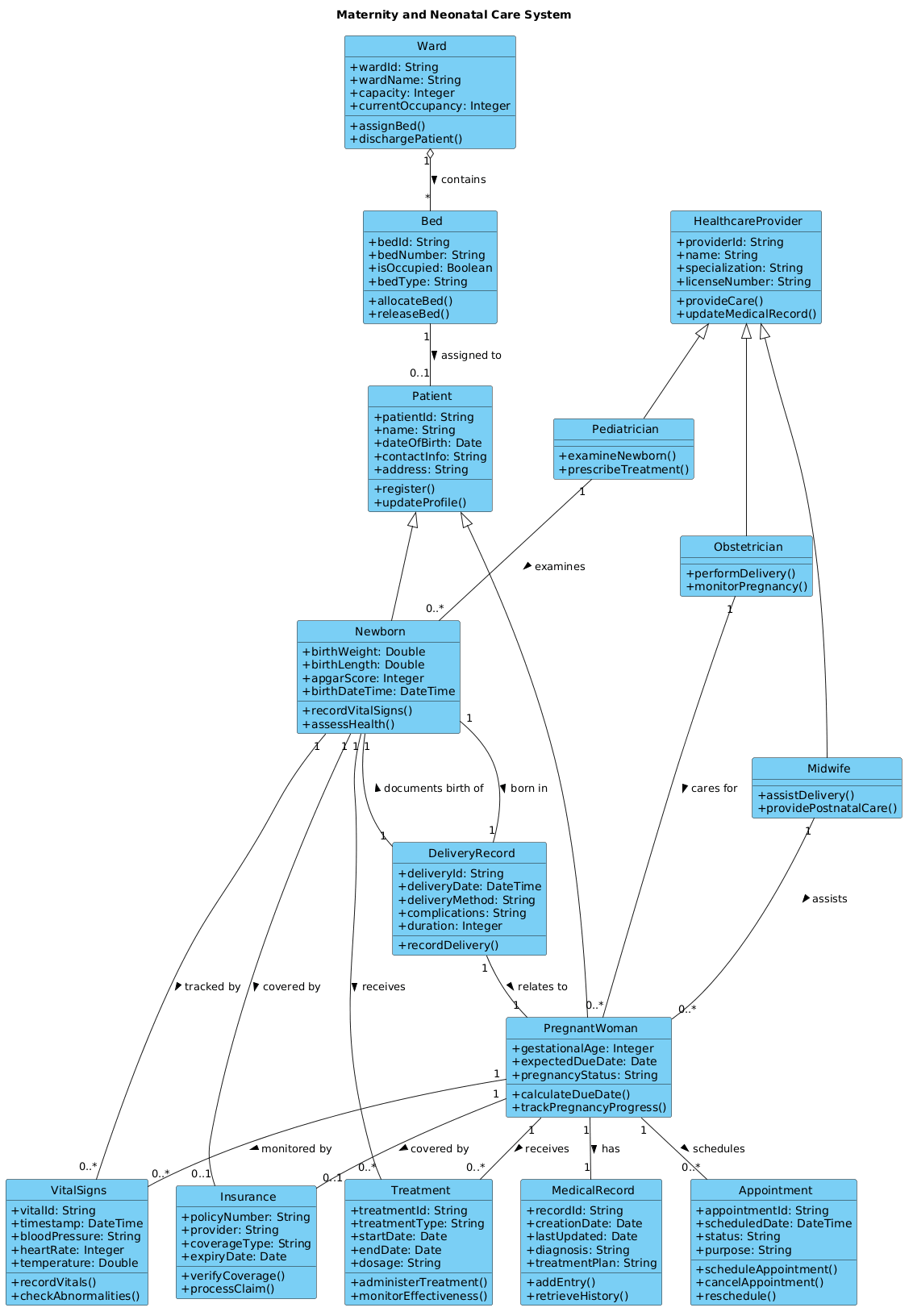
This specific diagram type models the static data architecture of the system. It answers questions like: What attributes does a Newborn possess? How is a HealthcareProvider related to a Patient? Does a Ward own Beds, or does it merely contain them? By using PlantUML, we can explicitly define inheritance (Generalization), ownership (Composition), and usage (Association) relationships, which are critical for database schema generation and backend logic implementation.
Target Domain Scope & Scenario
The scope of this model covers the entire lifecycle of maternal and infant care within a facility. We are modeling the transition from Prenatal (PregnantWoman) to Delivery (DeliveryRecord) and Neonatal (Newborn, VitalSigns) care. The boundaries include the patient hierarchy, the medical staff hierarchy, and the physical resources (Wards, Beds) required to support them. We intentionally exclude billing or insurance backend logic beyond the structural relationship to keep the diagram focused on clinical data integrity.
Key Takeaways & Educational Insights
By following this guide, you will gain the ability to:
- Define hierarchical relationships between patients (Patient > PregnantWoman > Newborn).
- Model complex healthcare roles using inheritance (HealthcareProvider > Obstetrician).
- Apply correct UML cardinalities to ensure data constraints are visually documented.
- Use VPasCode to instantly validate syntax and visualize changes in real-time.
Complete Diagram & Full Source Code
Below is the finished blueprint for the Maternity and Neonatal Care System. You can review the full structure and the specific relationships between entities before diving into the step-by-step construction.
@startuml
!include https://static.visual-paradigm.com/web/resources/plantuml-stdlib/themes/vp.puml

title Maternity and Neonatal Care System

/' This system manages the care of pregnant women during maternity,
   newborn babies during neonatal period, and coordinates healthcare
   professionals, medical records, appointments, and treatments.
   It handles patient tracking from prenatal care through delivery
   to postnatal and neonatal monitoring, ensuring comprehensive
   healthcare management for mothers and infants. '/


class Patient {
    +patientId: String
    +name: String
    +dateOfBirth: Date
    +contactInfo: String
    +address: String
    +register()
    +updateProfile()
}

class PregnantWoman {
    +gestationalAge: Integer
    +expectedDueDate: Date
    +pregnancyStatus: String
    +calculateDueDate()
    +trackPregnancyProgress()
}

class Newborn {
    +birthWeight: Double
    +birthLength: Double
    +apgarScore: Integer
    +birthDateTime: DateTime
    +recordVitalSigns()
    +assessHealth()
}

class HealthcareProvider {
    +providerId: String
    +name: String
    +specialization: String
    +licenseNumber: String
    +provideCare()
    +updateMedicalRecord()
}

class Obstetrician {
    +performDelivery()
    +monitorPregnancy()
}

class Pediatrician {
    +examineNewborn()
    +prescribeTreatment()
}

class Midwife {
    +assistDelivery()
    +providePostnatalCare()
}

class MedicalRecord {
    +recordId: String
    +creationDate: Date
    +lastUpdated: Date
    +diagnosis: String
    +treatmentPlan: String
    +addEntry()
    +retrieveHistory()
}

class Appointment {
    +appointmentId: String
    +scheduledDate: DateTime
    +status: String
    +purpose: String
    +scheduleAppointment()
    +cancelAppointment()
    +reschedule()
}

class Treatment {
    +treatmentId: String
    +treatmentType: String
    +startDate: Date
    +endDate: Date
    +dosage: String
    +administerTreatment()
    +monitorEffectiveness()
}

class DeliveryRecord {
    +deliveryId: String
    +deliveryDate: DateTime
    +deliveryMethod: String
    +complications: String
    +duration: Integer
    +recordDelivery()
}

class Ward {
    +wardId: String
    +wardName: String
    +capacity: Integer
    +currentOccupancy: Integer
    +assignBed()
    +dischargePatient()
}

class Bed {
    +bedId: String
    +bedNumber: String
    +isOccupied: Boolean
    +bedType: String
    +allocateBed()
    +releaseBed()
}

class VitalSigns {
    +vitalId: String
    +timestamp: DateTime
    +bloodPressure: String
    +heartRate: Integer
    +temperature: Double
    +recordVitals()
    +checkAbnormalities()
}

class Insurance {
    +policyNumber: String
    +provider: String
    +coverageType: String
    +expiryDate: Date
    +verifyCoverage()
    +processClaim()
}

Patient <|-- PregnantWoman
Patient <|-- Newborn
HealthcareProvider <|-- Obstetrician
HealthcareProvider <|-- Pediatrician
HealthcareProvider <|-- Midwife

PregnantWoman "1" -- "0..*" Appointment : schedules >
PregnantWoman "1" -- "1" MedicalRecord : has >
PregnantWoman "1" -- "0..*" Treatment : receives >
PregnantWoman "1" -- "0..*" VitalSigns : monitored by >

Newborn "1" -- "1" DeliveryRecord : born in >
Newborn "1" -- "0..*" VitalSigns : tracked by >
Newborn "1" -- "0..*" Treatment : receives >

Obstetrician "1" -- "0..*" PregnantWoman : cares for >
Pediatrician "1" -- "0..*" Newborn : examines >
Midwife "1" -- "0..*" PregnantWoman : assists >

Ward "1" o-- "*" Bed : contains >
Bed "1" -- "0..1" Patient : assigned to >

PregnantWoman "1" -- "0..1" Insurance : covered by >
Newborn "1" -- "0..1" Insurance : covered by >

DeliveryRecord "1" -- "1" PregnantWoman : relates to >
DeliveryRecord "1" -- "1" Newborn : documents birth of >

@endumlStep-by-Step Architectural Walkthrough
Now that you have the full picture, let’s deconstruct how to build this diagram in VPasCode, phase by phase. This approach ensures you maintain control over the design and understand the impact of every relationship.
Phase 1: Canvas Configuration & Layout Directives
Every professional PlantUML diagram begins with setup directives. In this healthcare context, we want a clean, readable layout that matches the VPasCode theme. We start by including the standard library theme to ensure consistent styling for class boxes and arrows.
@startuml
!include https://static.visual-paradigm.com/web/resources/plantuml-stdlib/themes/vp.puml

title Maternity and Neonatal Care System
The @startuml directive marks the beginning of the file. The !include command pulls in the visual theme from the Visual Paradigm CDN, giving your diagram a polished look without manual CSS. The title directive sets the caption for the diagram, which is crucial for documentation clarity.
Phase 2: Declaring Core Entities, Actors, and Boundaries
Next, we define the core classes. In a healthcare system, the hierarchy is vital. We start with the base Patient class, which acts as the parent for specific patient types.
class Patient {
    +patientId: String
    +name: String
    +dateOfBirth: Date
    +contactInfo: String
    +address: String
    +register()
    +updateProfile()
}

# Patient <|-- PregnantWoman
# Patient <|-- Newborn
We define the base attributes like patientId and name for all patients. Then, we introduce specialized classes like PregnantWoman and Newborn. Note that these inherit from Patient, meaning they automatically possess the base attributes while adding their own specific fields like gestationalAge or birthWeight. This generalization reduces redundancy in your design.
Phase 3: Mapping Data Flows & Key Interactions
With entities defined, we must establish how they interact. In PlantUML, relationships are drawn between class names. We use different arrow types to denote the nature of the relationship.
# Generalization (Inheritance)
HealthcareProvider <|-- Obstetrician
HealthcareProvider <|-- Pediatrician

# Association (Usage)
PregnantWoman "1" -- "0..*" Appointment : schedules

# Composition (Strong Ownership)
Ward "1" o-- "*" Bed : contains
The <|-- arrow represents inheritance (Generalization). The -- line represents a standard association. The o-- line with the diamond represents Composition, indicating that a Ward is composed of Beds; if the Ward is deleted, the Beds lose their context. Cardinality (e.g., 1, 0..*) is explicitly stated to define business rules, such as one Ward containing many Beds.
Phase 4: Grouping, Annotations & Visual Polish
Finally, we add context and polish. A comment block helps future developers understand the diagram’s intent without needing to read the code logic.
/' This system manages the care of pregnant women during maternity,
   newborn babies during neonatal period, and coordinates healthcare
   professionals, medical records, appointments, and treatments. '/

@enduml
The comment block wrapped in /' and '/ is invisible in the final diagram but remains in the source code for human readers. This ensures your documentation stays synchronized with your architecture.
Syntax & Keyword Deep Dive
To master PlantUML with VPasCode, you need to understand the specific keywords that drive the diagram’s logic. Here is a breakdown of the critical syntax used in this healthcare model.
class: Defines a new entity. The syntaxclass ClassName { attributes; methods; }creates a box with the specified properties.title: Sets the main heading of the diagram, essential for reports and documentation.!include: Imports external style files (like themes) to standardize the visual appearance.<|--: Represents Generalization (Inheritance). The arrow points to the parent class. Used here forPatientandHealthcareProviderhierarchies.--: Represents a standard Association. Used for relationships likePregnantWomanandAppointment.o--: Represents Composition. The filled diamond indicates a strong “part-of” relationship, used forWardandBed."0..*"/"1": Cardinality notations.0..*means zero or more, while1means exactly one. These define the constraints of the relationship./' ... '/: Multi-line comment syntax. Text inside is ignored by the renderer but visible in the source code.
Best Practices & Pitfalls to Avoid
Creating a healthcare diagram requires precision. Follow these best practices to ensure your VPasCode diagrams remain maintainable and accurate.
- Maintain Hierarchical Consistency: Ensure that child classes (like
Obstetrician) only override or extend attributes logically. Do not duplicate base attributes likenamein the child class if they exist inHealthcareProvider. - Use Clear Cardinalities: Ambiguous relationships lead to database errors. Always specify cardinality (e.g.,
"1"vs"0..*") to define if a relationship is mandatory or optional. - Keep Classes Focused: Avoid “God Classes” that contain too many attributes. If a class has too many methods, consider splitting it into logical sub-modules or related classes.
- Document with Comments: Use the
/'syntax to explain complex business logic that isn’t obvious from the class names alone. This is vital for onboarding new developers to the healthcare system.
Start Building PlantUML Diagrams Faster with VPasCode
Design complex healthcare schemas and class models instantly in your browser without installing any tools or configuring local environments.