


In the rapidly evolving landscape of 5G telecommunications, network architecture has shifted from hardware-centric appliances to cloud-native, software-defined solutions. This transformation introduces complex orchestration challenges where network functions must be dynamically deployed, scaled, and managed across distributed infrastructure. Visual modeling becomes critical in this environment to ensure system architects and developers have a clear, shared understanding of the static structure, dependencies, and resource boundaries within the 5G Core.

This tutorial demonstrates how to construct a professional 5G Core Orchestration System class diagram using PlantUML with VPasCode, the free web-based diagram-as-code editor. By leveraging VPasCode, you can prototype complex orchestration logic instantly without installing local Java environments or configuring build tools. This approach enhances architectural clarity, facilitates rapid visual prototyping, and serves as living technical documentation that evolves alongside your system design.
Understanding the Model: Purpose, Scope & Problem Framing
Diagram Abstraction & Representation
A class diagram in this context serves as the blueprint for the orchestration layer’s object-oriented design. It models the static structure of the system, defining classes that represent management entities, resource abstractions, and network functions. Unlike sequence diagrams that focus on runtime behavior, this diagram emphasizes the relationships between components: how the Orchestrator delegates tasks to the SliceManager, how InfrastructureManager aggregates resources, and how specific network functions like AMF or UPF inherit from a base NetworkFunction.
Target Domain Scope & Scenario
The scope of this model focuses on the control plane and management plane responsibilities within a 5G Core environment. It intentionally excludes the user plane data forwarding details to maintain clarity on the orchestration logic. The diagram covers key areas such as Network Slice lifecycle management, NFV (Network Functions Virtualization) resource allocation, service continuity, and fault recovery mechanisms. It defines the boundaries between high-level orchestration decisions and the underlying infrastructure resources.
Key Takeaways & Educational Insights
By building this model, you will gain insights into:
- Abstraction Layers: How to separate business logic (Slice Management) from infrastructure details (Compute/Storage Pools).
- Relationship Modeling: The distinction between composition (strong ownership), aggregation (weak ownership), and generalization (inheritance).
- Telecom Standards: How to map 5G concepts like Network Slicing and Network Functions into software architecture.
Complete Diagram & Full Source Code
Below is the finished blueprint for the 5G Core Orchestration System. You can visualize the relationships between the Orchestrator, NetworkSlice, and InfrastructureManager immediately.
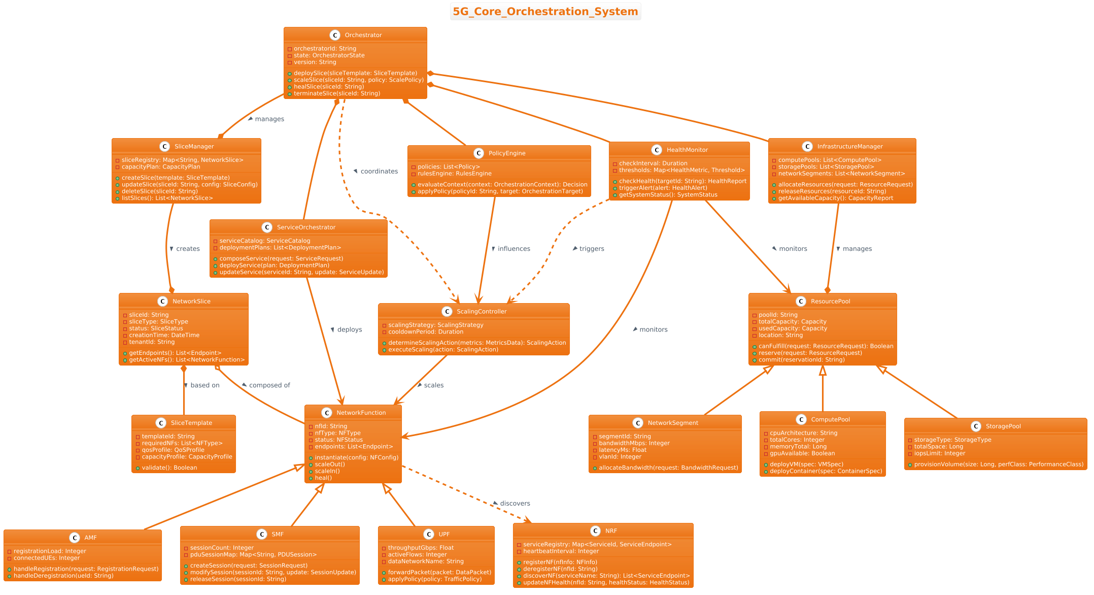
Copy the complete source code below to use in the VPasCode editor. This code includes the theme configuration, class definitions, and relationship mappings.
@startuml
!theme aws-orange
title 5G_Core_Orchestration_System

/'
 This class diagram models the orchestration layer for a 5G Core network.
 It captures the key management functions and resource abstractions needed
 to deploy, scale, and heal network services across a cloud-native infrastructure.
 The context includes Network Slice lifecycle management, NFV resource allocation,
 service continuity, and fault recovery, with clear separation between
 orchestration decision points and the underlying infrastructure resources.
'/

class Orchestrator {
  - orchestratorId: String
  - state: OrchestratorState
  - version: String
  + deploySlice(sliceTemplate: SliceTemplate)
  + scaleSlice(sliceId: String, policy: ScalePolicy)
  + healSlice(sliceId: String)
  + terminateSlice(sliceId: String)
}

class SliceManager {
  - sliceRegistry: Map<String, NetworkSlice>
  - capacityPlan: CapacityPlan
  + createSlice(template: SliceTemplate)
  + updateSlice(sliceId: String, config: SliceConfig)
  + deleteSlice(sliceId: String)
  + listSlices(): List<NetworkSlice>
}

class NetworkSlice {
  - sliceId: String
  - sliceType: SliceType
  - status: SliceStatus
  - creationTime: DateTime
  - tenantId: String
  + getEndpoints(): List<Endpoint>
  + getActiveNFs(): List<NetworkFunction>
}

class SliceTemplate {
  - templateId: String
  - requiredNFs: List<NFType>
  - qosProfile: QoSProfile
  - capacityProfile: CapacityProfile
  + validate(): Boolean
}

class InfrastructureManager {
  - computePools: List<ComputePool>
  - storagePools: List<StoragePool>
  - networkSegments: List<NetworkSegment>
  + allocateResources(request: ResourceRequest)
  + releaseResources(resourceId: String)
  + getAvailableCapacity(): CapacityReport
}

class ResourcePool {
  - poolId: String
  - totalCapacity: Capacity
  - usedCapacity: Capacity
  - location: String
  + canFulfill(request: ResourceRequest): Boolean
  + reserve(request: ResourceRequest)
  + commit(reservationId: String)
}

class ComputePool {
  - cpuArchitecture: String
  - totalCores: Integer
  - memoryTotal: Long
  - gpuAvailable: Boolean
  + deployVM(spec: VMSpec)
  + deployContainer(spec: ContainerSpec)
}

class StoragePool {
  - storageType: StorageType
  - totalSpace: Long
  - iopsLimit: Integer
  + provisionVolume(size: Long, perfClass: PerformanceClass)
}

class NetworkSegment {
  - segmentId: String
  - bandwidthMbps: Integer
  - latencyMs: Float
  - vlanId: Integer
  + allocateBandwidth(request: BandwidthRequest)
}

class NetworkFunction {
  - nfId: String
  - nfType: NFType
  - status: NFStatus
  - endpoints: List<Endpoint>
  + instantiate(config: NFConfig)
  + scaleOut()
  + scaleIn()
  + heal()
}

class AMF {
  - registrationLoad: Integer
  - connectedUEs: Integer
  + handleRegistration(request: RegistrationRequest)
  + handleDeregistration(ueId: String)
}

class SMF {
  - sessionCount: Integer
  - pduSessionMap: Map<String, PDUSession>
  + createSession(request: SessionRequest)
  + modifySession(sessionId: String, update: SessionUpdate)
  + releaseSession(sessionId: String)
}

class UPF {
  - throughputGbps: Float
  - activeFlows: Integer
  - dataNetworkName: String
  + forwardPacket(packet: DataPacket)
  + applyPolicy(policy: TrafficPolicy)
}

class NRF {
  - serviceRegistry: Map<ServiceId, ServiceEndpoint>
  - heartbeatInterval: Integer
  + registerNF(nfInfo: NFInfo)
  + deregisterNF(nfId: String)
  + discoverNF(serviceName: String): List<ServiceEndpoint>
  + updateNFHealth(nfId: String, healthStatus: HealthStatus)
}

class ServiceOrchestrator {
  - serviceCatalog: ServiceCatalog
  - deploymentPlans: List<DeploymentPlan>
  + composeService(request: ServiceRequest)
  + deployService(plan: DeploymentPlan)
  + updateService(serviceId: String, update: ServiceUpdate)
}

class HealthMonitor {
  - checkInterval: Duration
  - thresholds: Map<HealthMetric, Threshold>
  + checkHealth(targetId: String): HealthReport
  + triggerAlert(alert: HealthAlert)
  + getSystemStatus(): SystemStatus
}

class PolicyEngine {
  - policies: List<Policy>
  - rulesEngine: RulesEngine
  + evaluateContext(context: OrchestrationContext): Decision
  + applyPolicy(policyId: String, target: OrchestrationTarget)
}

class ScalingController {
  - scalingStrategy: ScalingStrategy
  - cooldownPeriod: Duration
  + determineScalingAction(metrics: MetricsData): ScalingAction
  + executeScaling(action: ScalingAction)
}

' === Relationships ===
Orchestrator --* SliceManager : manages >
Orchestrator *-- PolicyEngine
Orchestrator *-- HealthMonitor
Orchestrator *-- ServiceOrchestrator
Orchestrator *-- InfrastructureManager

SliceManager --* NetworkSlice : creates >
NetworkSlice *-- SliceTemplate : based on >
NetworkSlice o-- NetworkFunction : composed of >

InfrastructureManager --* ResourcePool : manages >
ResourcePool <|-- ComputePool
ResourcePool <|-- StoragePool
ResourcePool <|-- NetworkSegment

NetworkFunction <|-- AMF
NetworkFunction <|-- SMF
NetworkFunction <|-- UPF
NetworkFunction ..> NRF : discovers >

ServiceOrchestrator --> NetworkFunction : deploys >
ScalingController --> NetworkFunction : scales >
HealthMonitor --> NetworkFunction : monitors >
HealthMonitor --> ResourcePool : monitors >

PolicyEngine --> ScalingController : influences >
HealthMonitor ..> ScalingController : triggers >
Orchestrator ..> ScalingController : coordinates >
@endumlStep-by-Step Architectural Walkthrough
Constructing a complex class diagram requires a methodical approach. We will break down the creation of this 5G Core model into four distinct phases to ensure clarity and maintainability.
Phase 1: Canvas Configuration & Layout Directives
Before defining classes, we must set the visual environment. This ensures the diagram aligns with the desired aesthetic and provides context immediately.
First, we apply a theme to give the diagram a professional look consistent with cloud provider branding:
!theme aws-orangeNext, we add a title and a comment block. Comments in PlantUML are enclosed in slashes and provide essential context for readers without cluttering the visual output:
title 5G_Core_Orchestration_System

/'
 This class diagram models the orchestration layer for a 5G Core network.
 It captures the key management functions and resource abstractions needed
 to deploy, scale, and heal network services across a cloud-native infrastructure.
'/
Phase 2: Declaring Core Entities, Actors, and Boundaries
The heart of the orchestration system lies in the management classes. We start by defining the Orchestrator, which acts as the central entry point, and the SliceManager, which handles the lifecycle of network slices.
Define the attributes (private data) and methods (public actions) for the Orchestrator:
class Orchestrator {
  - orchestratorId: String
  - state: OrchestratorState
  + deploySlice(sliceTemplate: SliceTemplate)
  + scaleSlice(sliceId: String, policy: ScalePolicy)
}
Similarly, define the SliceManager to manage the registry of slices:
class SliceManager {
  - sliceRegistry: Map
  + createSlice(template: SliceTemplate)
  + updateSlice(sliceId: String, config: SliceConfig)
}
Phase 3: Mapping Data Flows & Key Interactions
In a class diagram, we map interactions through relationships rather than message flows. We define how the InfrastructureManager interacts with various resource pools. This section establishes the hierarchy of resources.
We declare the base ResourcePool class and its specific implementations like ComputePool and StoragePool. This prepares the ground for inheritance relationships:
class ResourcePool {
  - poolId: String
  - totalCapacity: Capacity
}

class ComputePool {
  - cpuArchitecture: String
  + deployVM(spec: VMSpec)
}
Phase 4: Grouping, Annotations & Visual Polish
The final phase involves connecting the classes to define ownership, usage, and inheritance. We use specific arrow styles to denote the type of relationship.
For example, the Orchestrator strongly owns the PolicyEngine (Composition), while it manages the SliceManager (Aggregation). We also define inheritance for Network Functions:
Orchestrator *-- PolicyEngine
NetworkFunction <|-- AMF
NetworkFunction <|-- SMF
This phase ensures the diagram accurately reflects the architectural constraints and responsibilities of the 5G Core system.
Syntax & Keyword Deep Dive
To master PlantUML class diagrams, it is essential to understand the specific syntax keywords used in this model. These keywords define the visual representation and the semantic meaning of the connections.
class: Defines a new class with its name and members. Attributes are prefixed with-(private) or+(public).title: Sets the main heading of the diagram.!theme: Applies a predefined color scheme and styling to the entire diagram.--*(Composition): Indicates a strong ownership relationship where the child cannot exist without the parent (e.g.,OrchestratorownsPolicyEngine).--o(Aggregation): Indicates a weak "has-a" relationship where the child can exist independently (e.g.,NetworkSliceaggregatesNetworkFunction).<|--(Generalization): Represents inheritance, where a child class inherits from a parent (e.g.,AMFextendsNetworkFunction)...>(Dependency): Indicates a usage relationship where one class depends on another (e.g.,NRFis discovered byNetworkFunction)./' ... '/(Comment): Wraps multi-line text that appears in the diagram but is not executable code.
Best Practices & Pitfalls to Avoid
When modeling complex systems like 5G Core orchestration, adhering to best practices ensures your diagrams remain maintainable and readable.
- Modularize Your Classes: Avoid creating a single massive class file. Group related classes (like
AMF,SMF,UPF) logically to make the diagram easier to scan. - Consistent Naming Conventions: Use clear, descriptive names for attributes and methods. Avoid abbreviations unless they are industry standard (e.g., use
NFTypeinstead ofNT). - Manage Visual Complexity: If the diagram becomes too crowded, consider splitting it into multiple diagrams (e.g., one for Infrastructure, one for Service Management) and linking them.
- Choose the Right Relationship: Distinguish carefully between Composition and Aggregation. Composition implies lifecycle dependency, while Aggregation implies shared existence.
Start Building 5G Core Class Diagrams Faster with VPasCode
Instantly prototype and customize your 5G Core orchestration diagrams in your browser without installing any tools or configuring environments.