


In the realm of government technology, ensuring the integrity of election data is paramount. An Election Management System (EMS) relies on robust workflows to verify voter eligibility without compromising security or accessibility. Sequence diagrams are the industry standard for modeling these time-dependent interactions, providing a clear blueprint of how actors communicate with system components.
However, traditional diagramming tools often require complex setups or manual drag-and-drop adjustments that slow down architectural planning. This is where VPasCode changes the game. As a free, web-based diagram-as-code tool, it allows architects to define complex government workflows using PlantUML syntax directly in the browser.
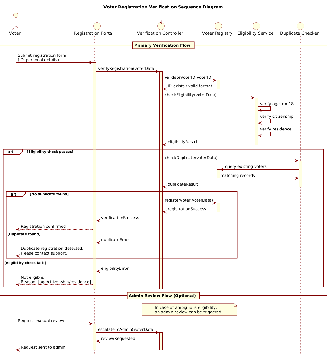
In this masterclass, we will construct a Voter Registration Verification Sequence Diagram. This model captures the critical path from voter submission to final eligibility approval, including error handling for duplicate registrations and age verification. By using VPasCode, you gain instant live rendering, allowing you to iterate on your logic without installing local dependencies.
Understanding the Model: Purpose, Scope & Problem Framing
Diagram Abstraction & Representation
A sequence diagram focuses on the temporal ordering of interactions. In this specific government context, it models the lifecycle of a registration request. It answers the question: “What happens when a voter submits data, and how does the system validate it before committing to the registry?”
Target Domain Scope & Scenario
The diagram boundaries are defined to include the public-facing Registration Portal, the backend Verification Controller, and the core data entities (Voter Registry, Eligibility Service, Duplicate Checker). It intentionally excludes external legacy systems to focus on the core verification logic.
Key Takeaways & Educational Insights
By building this model, you will learn how to manage complex conditional logic (such as eligibility checks vs. duplicate checks) using PlantUML combined fragments. You will also see how to visualize activation bars to understand component load and state.
Complete Diagram & Full Source Code
Before diving into the construction steps, here is the final blueprint. You can view the rendered result immediately in the VPasCode editor.
@startuml
!include https://static.visual-paradigm.com/web/resources/plantuml-stdlib/themes/rose.puml

title Voter Registration Verification Sequence Diagram

/'
  This sequence diagram illustrates the voter registration verification process
  within an Election Management System (EMS). It covers:
  - Initial validation of voter ID and personal details
  - Eligibility checks (age, citizenship, residence)
  - Duplicate registration detection
  - Alternative flows for invalid or duplicate registrations
  - Final approval or rejection of the registration request
'/

actor "Voter" as Voter
boundary "Registration Portal" as Portal
control "Verification Controller" as Controller
entity "Voter Registry" as Registry
entity "Eligibility Service" as Eligibility
entity "Duplicate Checker" as Duplicate

== Primary Verification Flow ==

Voter -> Portal: Submit registration form\n(ID, personal details)
activate Portal

Portal -> Controller: verifyRegistration(voterData)
activate Controller

Controller -> Registry: validateVoterID(voterID)
activate Registry
Registry --> Controller: ID exists / valid format
deactivate Registry

Controller -> Eligibility: checkEligibility(voterData)
activate Eligibility

Eligibility -> Eligibility: verify age >= 18
Eligibility -> Eligibility: verify citizenship
Eligibility -> Eligibility: verify residence

Eligibility --> Controller: eligibilityResult
deactivate Eligibility

alt Eligibility check passes
    Controller -> Duplicate: checkDuplicate(voterData)
    activate Duplicate

    Duplicate -> Registry: query existing voters
    activate Registry
    Registry --> Duplicate: matching records
    deactivate Registry

    Duplicate --> Controller: duplicateResult
    deactivate Duplicate

    alt No duplicate found
        Controller -> Registry: registerVoter(voterData)
        activate Registry
        Registry --> Controller: registrationSuccess
        deactivate Registry

        Controller --> Portal: verificationSuccess
        Portal --> Voter: Registration confirmed
    else Duplicate found
        Controller --> Portal: duplicateError
        Portal --> Voter: Duplicate registration detected.\nPlease contact support.
    end
else Eligibility check fails
    Controller --> Portal: eligibilityError
    Portal --> Voter: Not eligible.\nReason: [age/citizenship/residence]
end

deactivate Controller
deactivate Portal

== Admin Review Flow (Optional) ==

note over Controller, Registry
  In case of ambiguous eligibility,
  an admin review can be triggered
end note

Voter -> Portal: Request manual review
activate Portal
Portal -> Controller: escalateToAdmin(voterData)
activate Controller
Controller --> Portal: reviewRequested
Portal --> Voter: Request sent to admin
deactivate Controller
deactivate Portal
@endumlStep-by-Step Architectural Walkthrough
Now, let’s break down the construction process into four distinct phases. This approach ensures your diagram remains maintainable and logically sound.
Phase 1: Canvas Configuration & Layout Directives
Every professional PlantUML diagram starts with configuration. We begin by including a theme to ensure visual consistency. The rose.puml theme provides a clean, modern aesthetic suitable for government documentation.
!include https://static.visual-paradigm.com/web/resources/plantuml-stdlib/themes/rose.puml

title Voter Registration Verification Sequence Diagram

/'
  This sequence diagram illustrates the voter registration verification process
  within an Election Management System (EMS). It covers:
  - Initial validation of voter ID and personal details
  - Eligibility checks (age, citizenship, residence)
  - Duplicate registration detection
  - Alternative flows for invalid or duplicate registrations
  - Final approval or rejection of the registration request
'/
Notice the use of the title directive for the main heading and the comment block /' ... '/. This metadata is crucial for documentation purposes, ensuring anyone viewing the diagram understands its scope immediately.
Phase 2: Declaring Core Entities, Actors, and Boundaries
Next, we define the participants. In PlantUML, we use specific stereotypes to denote the nature of each component. This helps stakeholders distinguish between human users and system services.
actor "Voter" as Voter
boundary "Registration Portal" as Portal
control "Verification Controller" as Controller
entity "Voter Registry" as Registry
entity "Eligibility Service" as Eligibility
entity "Duplicate Checker" as Duplicate
Here, actor represents the human user. boundary represents the user interface (the Portal). control represents the logic handler (Controller). entity represents data storage or external services. Using these distinct types improves readability significantly.
Phase 3: Mapping Data Flows & Key Interactions
With participants defined, we map the primary flow. We use solid arrows -> for synchronous requests and dashed arrows --> for responses. Activation bars activate and deactivate visualize when a component is busy processing.
Voter -> Portal: Submit registration form\
(ID, personal details)
activate Portal

Portal -> Controller: verifyRegistration(voterData)
activate Controller
We also utilize combined fragments like alt (alternative) to handle conditional logic. In this diagram, we nest alt blocks to handle eligibility checks first, and then duplicate checks only if eligibility passes. This mirrors real-world business logic where you don’t check for duplicates if the user isn’t eligible.
Phase 4: Grouping, Annotations & Visual Polish
Finally, we add context. A note block is used to indicate optional flows, such as the Admin Review scenario. This keeps the primary flow clean while documenting edge cases.
note over Controller, Registry
  In case of ambiguous eligibility,
  an admin review can be triggered
end note
Using VPasCode, you can adjust the theme or alignment instantly to ensure the note fits perfectly within the layout without manual pixel-pushing.
Syntax & Keyword Deep Dive
To master this diagram, you need to understand the specific PlantUML keywords used:
actor: Defines a human participant interacting with the system. In this case, the “Voter”.boundary: Represents the interface layer, such as the web “Registration Portal”.control: Represents the logic controller that coordinates actions, like the “Verification Controller”.entity: Represents data stores or external services, such as the “Voter Registry” or “Eligibility Service”.->(Solid Arrow): Indicates a synchronous message or request sent from one object to another.-->(Dashed Arrow): Indicates a return message or response.activate/deactivate: Toggles the vertical activation bar on a lifeline, showing when an object is actively processing a task.alt/else/end: Creates a combined fragment for alternative paths. The