


In the high-stakes environment of modern e-commerce, the checkout process is the critical juncture where user intent converts into business revenue. For software architects and product managers, visualizing this workflow is not merely a documentation exercise; it is a strategic necessity. A complex checkout flow involves intricate interactions between user interfaces, backend validation services, payment gateways, and inventory management systems. Misunderstandings in this logic can lead to abandoned carts, failed transactions, or inventory discrepancies.

Traditional drag-and-drop diagramming tools often struggle to maintain consistency as workflows evolve. Diagram-as-code tools offer a superior alternative for technical teams. By using PlantUML within the VPasCode editor, architects can define complex business logic, conditional branching, and parallel processes using plain text. This approach ensures that the visual model remains synchronized with the system requirements, facilitating rapid prototyping and clear communication between development and stakeholder teams.
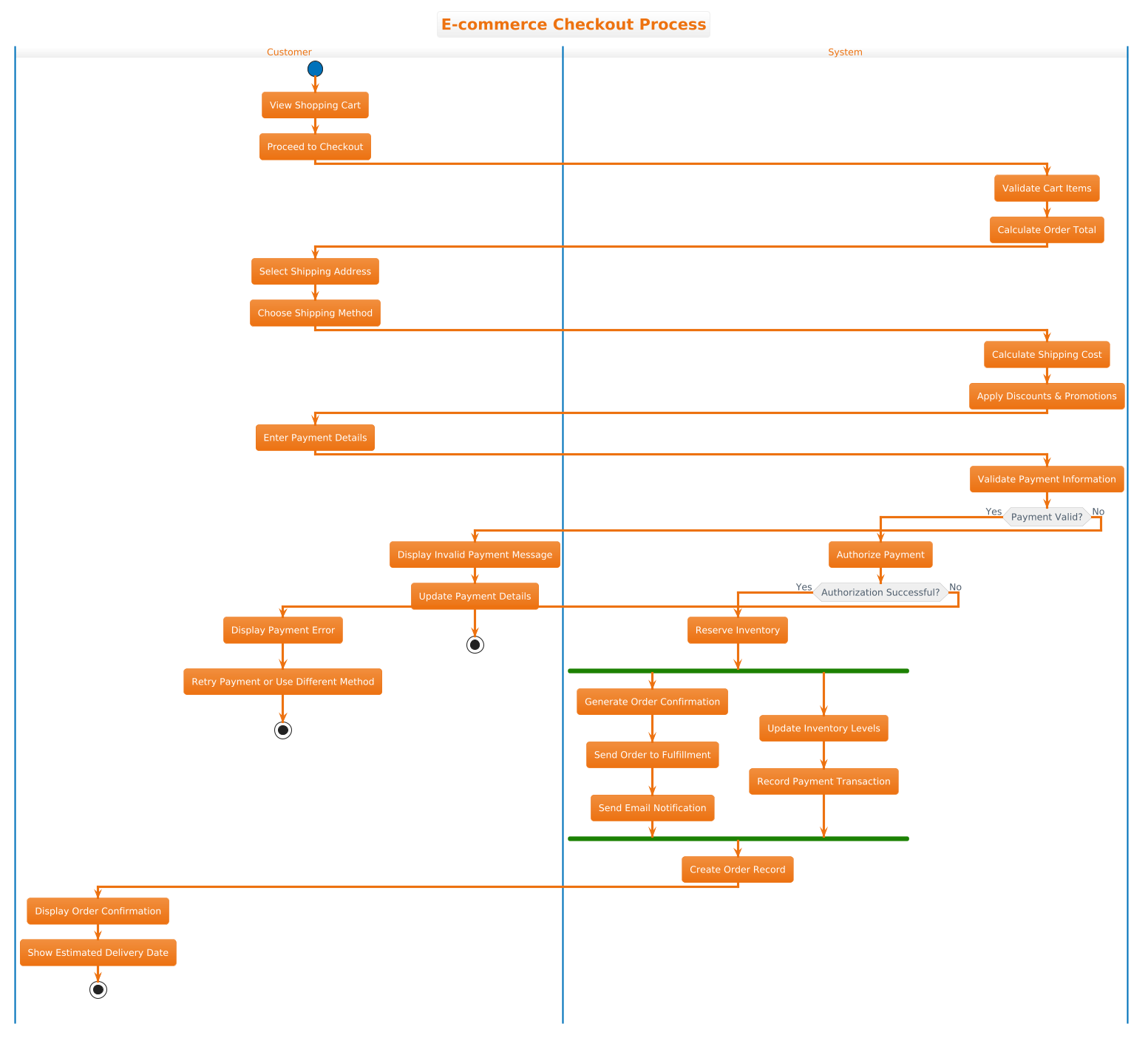
This masterclass utilizes VPasCode, the free web-based diagram-as-code editor, to construct a professional PlantUML activity diagram. We will build a comprehensive model of an E-commerce Checkout Process, demonstrating how to leverage swimlanes to distinguish between user actions and system responsibilities, while incorporating conditional logic and parallel execution flows.
Understanding the Model: Purpose, Scope & Problem Framing
Before writing a single line of code, it is essential to understand the abstraction and domain scope we are modeling. This diagram is not a high-level user story; it is a detailed process blueprint intended to guide backend logic implementation.
Diagram Abstraction & Representation
An Activity Diagram in PlantUML is ideal for modeling the dynamic behavior of a system. Unlike a static class diagram, an activity diagram captures the flow of control and data. In this specific context, the diagram represents a state machine where the process moves from a “Start” state through various decision points and actions until it reaches a “Stop” state.
We will utilize Swimlanes (vertical partitions) to categorize responsibilities. This visual separation is critical for clarity:
- Customer Lane: Represents actions initiated by the human user (e.g., viewing the cart, entering payment details).
- System Lane: Represents automated backend processes (e.g., validating cart items, calculating totals, authorizing payments).
Target Domain Scope & Scenario
The scope of this diagram covers the critical path from the moment a customer decides to check out until the order is confirmed. It intentionally excludes pre-checkout activities like “Add to Cart” and post-checkout activities like “Shipping Tracking.” The focus is strictly on the transactional integrity of the checkout event.
The scenario addresses a standard retail environment where inventory must be reserved, payments must be validated asynchronously, and notifications must be sent in parallel to ensure a responsive user experience.
Key Takeaways & Educational Insights
By completing this tutorial, you will gain the ability to:
- Structure complex workflows using swimlanes to separate concerns.
- Implement conditional logic (if/else) to handle success and error paths.
- Model parallel processing using
forkandfork againto simulate concurrent system tasks. - Apply visual themes to align diagrams with enterprise branding standards.
Complete Diagram & Full Source Code
Below is the finished blueprint for the E-commerce Checkout Process. This code is designed to be pasted directly into the VPasCode editor to render the preview instantly.
@startuml
!theme aws-orange
title E-commerce Checkout Process

|Customer|
start
:View Shopping Cart;
:Proceed to Checkout;

|System|
:Validate Cart Items;
:Calculate Order Total;

|Customer|
:Select Shipping Address;
:Choose Shipping Method;

|System|
:Calculate Shipping Cost;
:Apply Discounts & Promotions;

|Customer|
:Enter Payment Details;

|System|
:Validate Payment Information;

if (Payment Valid?) then (Yes)
  :Authorize Payment;
  if (Authorization Successful?) then (Yes)
    :Reserve Inventory;
    fork
      :Generate Order Confirmation;
      :Send Order to Fulfillment;
      :Send Email Notification;
    fork again
      :Update Inventory Levels;
      :Record Payment Transaction;
    end fork
    :Create Order Record;
    |Customer|
    :Display Order Confirmation;
    :Show Estimated Delivery Date;
    stop
  else (No)
    |Customer|
    :Display Payment Error;
    :Retry Payment or Use Different Method;
    stop
  endif
else (No)
  |Customer|
  :Display Invalid Payment Message;
  :Update Payment Details;
  stop
endif
@endumlStep-by-Step Architectural Walkthrough
Constructing this diagram in VPasCode involves four logical phases. We will build the skeleton first, then populate the lanes, define the logic, and finally apply the visual polish.
Phase 1: Canvas Configuration & Layout Directives
Every PlantUML diagram begins with global directives that set the rendering engine’s behavior. In this model, we start by defining the visual theme and the diagram title. This ensures the output matches the requested branding immediately.
We use the !theme directive to apply a pre-defined color palette. For this retail scenario, the aws-orange theme provides a professional, warm color scheme suitable for e-commerce applications.
!theme aws-orange
title E-commerce Checkout Process
Phase 2: Declaring Core Entities, Actors, and Boundaries
Next, we define the swimlanes. In PlantUML, swimlanes are declared using vertical bars | around the lane name. This creates a vertical partition in the diagram where subsequent nodes will reside until a new lane is declared.
We alternate between the Customer and System lanes to reflect the hand-off points in the workflow. For example, the customer views the cart, then the system takes over to validate the items.
|Customer|
start
:View Shopping Cart;
:Proceed to Checkout;

|System|
:Validate Cart Items;
:Calculate Order Total;
Phase 3: Mapping Data Flows & Key Interactions
The core logic of the diagram lies in the decision points. We use the if keyword to create branching paths based on validation results. Each branch is labeled (e.g., Yes or No) to indicate the condition outcome.
In the checkout flow, payment validation is the most critical decision point. If the payment is invalid, the flow terminates early to prevent inventory reservation errors. If valid, the flow proceeds to authorization.
if (Payment Valid?) then (Yes)
  :Authorize Payment;
  if (Authorization Successful?) then (Yes)
    :Reserve Inventory;
    ...
Phase 4: Grouping, Annotations & Visual Polish
Finally, we handle parallel processing. In a real-world e-commerce system, multiple tasks happen simultaneously after an order is authorized (e.g., sending an email and updating inventory). We use the fork and end fork syntax to represent these concurrent threads.
This ensures the diagram accurately reflects the system’s ability to handle non-blocking operations, improving the perceived performance for the user. We conclude the flow with a stop node to clearly mark the end of the process.
fork
  :Generate Order Confirmation;
  :Send Order to Fulfillment;
  :Send Email Notification;
fork again
  :Update Inventory Levels;
  :Record Payment Transaction;
end fork
Syntax & Keyword Deep Dive
To master PlantUML activity diagrams, you must understand the specific keywords used in this model. Here is a breakdown of the essential syntax elements:
!theme: A directive that applies a specific color scheme to the entire diagram. VPasCode supports various built-in themes to match your brand identity.|Lane|: Defines a swimlane. Any activity placed after this tag belongs to that specific actor until a new lane tag appears.start&stop: Mandatory nodes that mark the entry and exit points of the activity flow.:Action;: The standard syntax for defining an activity. The colon indicates an action node, and the semicolon terminates the line.if (Condition) then (Label): Creates a diamond-shaped decision node. The text inside(Condition)is the query, and(Label)is the text displayed on the arrow leading to the “Yes” branch.fork/fork again/end fork: These keywords define a parallel execution block. Activities betweenforkandfork againhappen simultaneously with activities betweenfork againandend fork.
Best Practices & Pitfalls to Avoid
When creating activity diagrams with PlantUML in VPasCode, adhere to these best practices to ensure maintainability and clarity:
- Maintain Swimlane Integrity: Avoid jumping between lanes too frequently without a clear reason. Each lane switch should represent a logical hand-off or data dependency.
- Limit Decision Depth: While nested
ifstatements are powerful, excessive nesting can make the diagram hard to read. If a path becomes too complex, consider breaking it into a sub-process or a separate diagram. - Use Descriptive Labels: Avoid generic labels like “Process Data.” Use specific terms like “Validate Payment Information” to ensure the diagram serves as accurate documentation.
- Visual Consistency: Stick to one theme per diagram. VPasCode allows you to preview the
!themechanges instantly, so use this to test which colors best highlight critical paths.
Start Building Activity Diagrams Faster with VPasCode
Instantly prototype, preview, and customize your workflow models online in VPasCode without installing any tools or configuring environments.