


In the fast-paced world of financial technology, clarity in process automation is not just a convenience—it is a compliance necessity. Debt collection systems rely on precise, automated workflows to manage customer communications, track outstanding balances, and escalate accounts appropriately. A single misstep in this logic can lead to regulatory issues or poor customer experiences. This is where visual modeling becomes critical. By translating text-based requirements into visual diagrams, architects and developers can validate the flow of logic before a single line of production code is written.

This tutorial focuses on the Payment Reminder Process within a Debt Collection System. We will use PlantUML to create an activity diagram that captures the system’s decision-making capabilities, including parallel communication channels (email, SMS, push notifications) and conditional branching based on payment status. Using VPasCode, the free web-based diagram-as-code editor, we can prototype, test, and refine this financial workflow instantly without the need for local software installation or environment configuration.
Understanding the Model: Purpose, Scope & Problem Framing
Before diving into the syntax, it is essential to understand the abstraction we are modeling. An activity diagram is ideal for this scenario because it maps the dynamic behavior of a system over time, rather than its static structure.
Diagram Abstraction & Representation
In the context of finance, activity diagrams serve as a blueprint for business rules. The swimlanes in this diagram represent the system boundaries, ensuring we understand which actions are automated by the backend versus those that require external triggers. The forks represent parallel processing, a common pattern in notification systems where multiple channels must be triggered simultaneously to maximize reach. The conditional nodes (if/else) represent the critical decision points where the system branches based on data states, such as whether a balance exists or if a payment has been received.
Target Domain Scope & Scenario
This model specifically covers the reminder lifecycle. It does not model the initial loan origination or the final legal collection stages, but rather the intermediate automated engagement phase. The scope includes:
- Receiving the trigger to initiate a reminder.
- Generating content based on the severity of the debt (1st, 2nd, Final).
- Distributing notifications via multiple channels.
- Handling the response (payment received vs. no response).
- Escalation logic if the threshold of reminders is reached.
Key Takeaways & Educational Insights
By building this model, you will gain insights into:
- Parallelism: How to model sending multiple notifications without waiting for one to complete before starting another.
- State Management: How to visually represent the transition from “reminder sent” to “payment received” or “escalated”.
- Visual Clarity: How to use swimlanes to keep the logic readable even when the process is complex.
Complete Diagram & Full Source Code
Below is the finished blueprint for the Debt Collection Payment Reminder Process. You can copy this code directly into the VPasCode editor to see the live rendering.
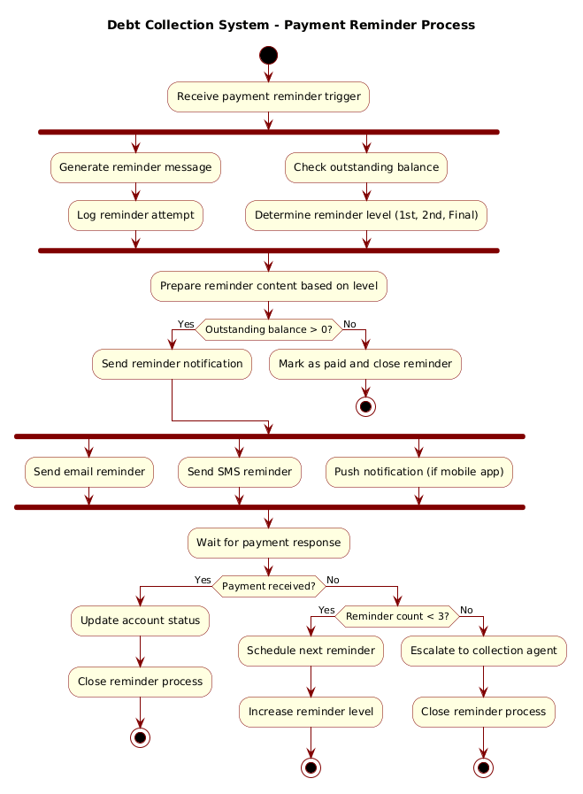
@startuml
!include https://static.visual-paradigm.com/web/resources/plantuml-stdlib/themes/rose.puml

title Debt Collection System - Payment Reminder Process

|System|
start
:Receive payment reminder trigger;

|System|
fork
  :Generate reminder message;
  :Log reminder attempt;
fork again
  :Check outstanding balance;
  :Determine reminder level (1st, 2nd, Final);
end fork

|System|
:Prepare reminder content based on level;

|System|
if (Outstanding balance > 0?) then (Yes)
  :Send reminder notification;
else (No)
  :Mark as paid and close reminder;
  stop
endif

|System|
fork
  :Send email reminder;
fork again
  :Send SMS reminder;
fork again
  :Push notification (if mobile app);
end fork

|System|
:Wait for payment response;

|System|
if (Payment received?) then (Yes)
  :Update account status;
  :Close reminder process;
  stop
else (No)
  if (Reminder count < 3?) then (Yes)
    :Schedule next reminder;
    :Increase reminder level;
    stop
  else (No)
    :Escalate to collection agent;
    :Close reminder process;
    stop
  endif
endif
@endumlStep-by-Step Architectural Walkthrough
Building this diagram requires a structured approach. We will break the construction into four logical phases: configuration, entity declaration, flow mapping, and visual polishing.
Phase 1: Canvas Configuration & Layout Directives
Every PlantUML diagram begins with setup. We need to define the theme to ensure the diagram looks professional and consistent with enterprise standards. We also set the title to provide immediate context.
!include https://static.visual-paradigm.com/web/resources/plantuml-stdlib/themes/rose.puml

title Debt Collection System - Payment Reminder Process
The !include directive loads the rose.puml theme, which provides a clean, modern aesthetic suitable for financial documentation. The title directive ensures the diagram has a clear heading when rendered.
Phase 2: Declaring Core Entities, Actors, and Boundaries
Next, we define the swimlanes. In this financial system, the entire process is handled by the automated backend, so we use a single |System| swimlane. This keeps the focus on the logic flow rather than separating human actors from machines.
|System|
start
:Receive payment reminder trigger;
The start node marks the entry point of the process, triggered by an external event (e.g., a scheduled cron job or a customer portal action). The first action is to receive the trigger.
Phase 3: Mapping Data Flows & Key Interactions
This is the core of the logic. We need to handle parallel processing for notifications and conditional logic for balance checks.
fork
  :Generate reminder message;
  :Log reminder attempt;
fork again
  :Check outstanding balance;
  :Determine reminder level (1st, 2nd, Final);
end fork
The fork keyword allows us to split the flow. Here, we split the process into two parallel tracks: generating the message and checking the balance. This ensures the system doesn’t wait for one to finish before starting the other, optimizing performance.
Following the fork, we handle the decision logic:
if (Outstanding balance > 0?) then (Yes)
  :Send reminder notification;
else (No)
  :Mark as paid and close reminder;
  stop
endif
The if/else block checks the data state. If the balance is zero, the process terminates early with stop. This is a critical optimization to avoid sending unnecessary reminders.
Phase 4: Grouping, Annotations & Visual Polish
Finally, we handle the multi-channel notification and the escalation logic. We use another fork to send Email, SMS, and Push notifications simultaneously.
fork
  :Send email reminder;
fork again
  :Send SMS reminder;
fork again
  :Push notification (if mobile app);
end fork
After sending, we wait for a response. If no payment is received after three attempts, the process escalates. This final phase ensures the diagram captures the full lifecycle of the reminder, from initiation to resolution or escalation.
Syntax & Keyword Deep Dive
To master PlantUML activity diagrams, you must understand the specific keywords used to control flow and structure. Here is a breakdown of the syntax features utilized in this finance workflow model.
title: Sets the main title of the diagram. This is essential for documentation and when embedding the diagram in reports.|Swimlane|: Defines a horizontal section of the diagram. In this model,|System|groups all actions performed by the automated backend.start/stop: Marks the beginning and end of the process flow. Multiplestopnodes are valid, representing different exit conditions (e.g., payment received vs. escalation).fork/fork again/end fork: Enables parallel processing.forksplits the flow,fork againadds more parallel branches, andend forkmerges them back together.if/then/else: Creates conditional branching. The text inside parentheses (e.g.,(Outstanding balance > 0?)) defines the condition, while(Yes)and(No) label the outgoing arrows.:Action;: Defines a specific process step or activity. The colon indicates an action, and the semicolon terminates the line.
Best Practices & Pitfalls to Avoid
When modeling complex financial workflows in VPasCode, adhering to best practices ensures your diagrams remain maintainable and readable.
- Limit Swimlane Depth: While multiple swimlanes can be useful, too many can clutter the view. In this case, a single
|System|lane was sufficient because the logic is backend-driven. If human actors were involved, separate lanes would be appropriate. - Keep Conditions Simple: Avoid nested
ifstatements deeper than two levels. If a decision tree becomes too complex, consider breaking the diagram into sub-processes or using a sequence diagram for that specific interaction. - Consistent Naming: Use clear, action-oriented names for activities (e.g.,
:Send reminder notification;rather than:Do something;). This makes the diagram self-documenting. - Visual Hierarchy: Use the
skinparamdirectives to ensure consistent colors and shapes. The rose.puml theme provides a professional look, but customizing colors for specific statuses (e.g., red for escalation) can enhance clarity.
Try It Yourself with VPasCode
Start Building PlantUML Activity Diagrams Faster with VPasCode
Instantly visualize your finance workflows with zero installation. Edit code, preview diagrams, and customize themes directly in your browser.