


Architectural Context: Visualizing Compliance in Finance
In the high-stakes environment of financial services and enterprise governance, clarity is not just a design preference—it is a regulatory requirement. An Audit Management System serves as the backbone for internal controls, ensuring that financial records are accurate, processes are followed, and compliance standards are met. However, translating these complex regulatory requirements into a functional software architecture can be challenging without a shared visual language.
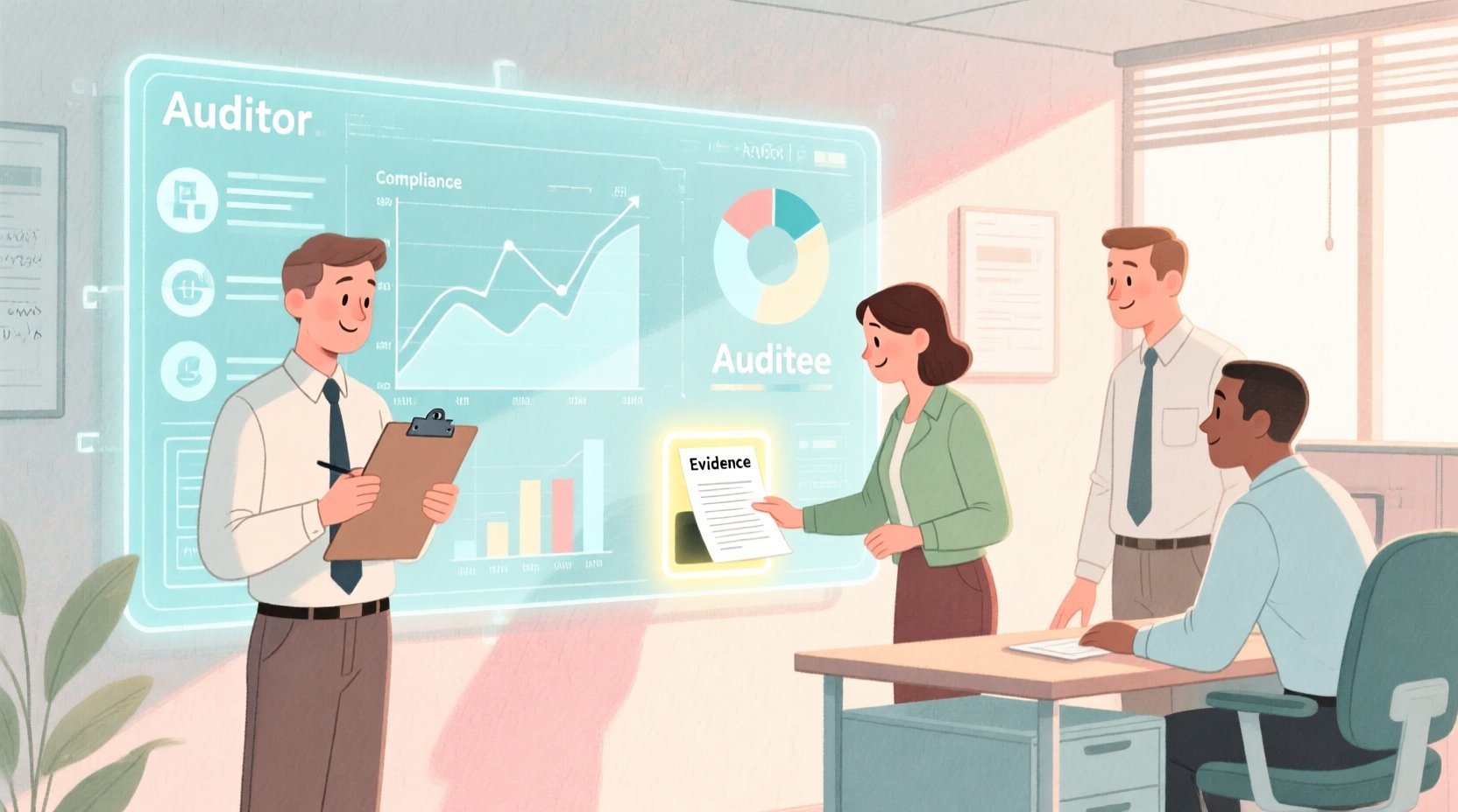
This is where diagramming-as-code with PlantUML transforms the development lifecycle. By using a text-based approach to define system boundaries and user interactions, architects can maintain living documentation that evolves alongside the code. Using VPasCode, a free web-based PlantUML editor, teams can instantly render these models to validate requirements before a single line of backend code is written. This tutorial focuses on constructing a robust Use Case Diagram for an Audit Management System, illustrating how to map critical actors—Auditors, Auditees, and Administrators—to their respective functional goals within the system boundary.
Understanding the Model: Purpose, Scope & Problem Framing
Diagram Abstraction & Representation
A Use Case Diagram is a behavioral modeling tool that captures what a system does from the perspective of its users. In the context of an Audit Management System, this diagram abstracts away technical implementation details (like database schemas or API endpoints) to focus on the functional interactions between the system and its human stakeholders.
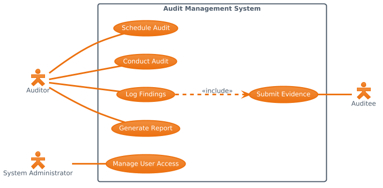
Each actor represents a specific role (e.g., “Auditor”) with a distinct set of responsibilities. Each use case represents a high-level goal (e.g., “Generate Report”) that the actor wishes to achieve. The lines connecting them define the scope of access: which roles can trigger which processes.
Target Domain Scope & Scenario
This diagram models the core workflow of a financial audit platform. The scope is intentionally bounded to the primary audit lifecycle:
- Preparation: Scheduling audits and managing user access.
- Execution: Conducting the audit and collecting evidence.
- Reporting: Logging findings and generating final compliance reports.
Dependencies are explicitly modeled, such as the requirement for an Auditee to submit evidence before an Auditor can log findings. This ensures the logical flow of the audit process is preserved in the architecture.
Key Takeaways & Educational Insights
By building this model, you will gain insights into:
- Role-Based Access Control (RBAC): Visualizing which actors have permissions for specific actions.
- Process Dependencies: Understanding how one use case (Evidence Submission) enables another (Logging Findings).
- System Boundaries: Clearly defining what is inside the “Audit Management System” versus external actors.
Complete Diagram & Full Source Code
Below is the final blueprint for the Audit Management System. You can view the rendered result immediately, and the code block below is interactive—click “Edit in VPasCode” to modify this diagram live in your browser.
@startuml
!theme aws-orange
left to right direction
skinparam actorStyle hollow

actor "Auditor" as Auditor
actor "Auditee" as Auditee
actor "System Administrator" as Admin

rectangle "Audit Management System" {
  usecase "Schedule Audit" as UC1
  usecase "Conduct Audit" as UC2
  usecase "Log Findings" as UC3
  usecase "Submit Evidence" as UC4
  usecase "Generate Report" as UC5
  usecase "Manage User Access" as UC6
}

Auditor -- UC1
Auditor -- UC2
Auditor -- UC3
Auditor -- UC5

UC4 -- Auditee

Admin -- UC6

UC3 ..> UC4 : <<include>>
@endumlStep-by-Step Architectural Walkthrough
Let us deconstruct the creation of this diagram into four logical phases. This approach ensures you understand not just how to type the code, but why specific directives are used to achieve professional visual results.
Phase 1: Canvas Configuration & Layout Directives
Before defining any entities, we set the stage. In VPasCode, you can instantly apply visual themes and layout directions to match your organization’s branding or documentation standards.
We begin with the @startuml directive to initialize the diagram. Next, we apply the !theme aws-orange directive. This specific theme applies a professional, warm color palette suitable for financial or enterprise documentation, ensuring the diagram looks polished immediately.
Finally, we set the flow direction:
left to right directionThis ensures the actors on the left and the system on the right creates a natural left-to-right reading flow, which is standard for most Western documentation.
Phase 2: Declaring Core Entities, Actors, and Boundaries
Actors represent the external users of the system. In PlantUML, we declare them using the actor keyword. We assign them unique IDs (like Auditor) to reference them later in relationships.
actor "Auditor" as Auditor
actor "Auditee" as Auditee
actor "System Administrator" as Admin
Notice the skinparam actorStyle hollow command. This customizes the visual appearance of the stick figures, giving them a modern, hollow outline rather than a filled silhouette. This subtle styling choice improves readability in complex diagrams.
Next, we define the system boundary using a rectangle. Everything inside this box belongs to the “Audit Management System”.
rectangle "Audit Management System" {
  // Use cases go here
}
Phase 3: Mapping Data Flows & Key Interactions
Inside the system boundary, we define the usecase elements. Each use case represents a specific functional goal. We assign them IDs (UC1, UC2, etc.) for easier reference in relationship lines.
usecase "Schedule Audit" as UC1
usecase "Conduct Audit" as UC2
usecase "Log Findings" as UC3
usecase "Submit Evidence" as UC4
usecase "Generate Report" as UC5
usecase "Manage User Access" as UC6
Now, we connect the actors to the use cases. The solid line (--) represents a standard association, indicating that the actor participates in that use case.
Auditor -- UC1
Auditor -- UC2
Auditor -- UC3
Auditor -- UC5
Here, we see the Auditor is the primary user, capable of scheduling, conducting, logging, and generating reports. The Admin is restricted to user management:
Admin -- UC6Phase 4: Grouping, Annotations & Visual Polish
Complex systems often have dependencies between use cases. In this scenario, an Auditor cannot log findings (UC3) without the Auditee submitting evidence (UC4) first. This is modeled as an include relationship.
We use a dashed line (..>) to indicate this dependency. The label <<include>> explicitly states that UC3 requires the functionality of UC4.
UC3 ..> UC4 : <<include>>Finally, we connect the Auditee to the evidence submission:
UC4 -- AuditeeThis completes the logical flow: The Auditee submits evidence, which is then included in the Auditor’s process of logging findings.
Syntax & Keyword Deep Dive
Understanding the specific PlantUML syntax allows you to extend this diagram further. Here are the critical keywords used in this model:
actor: Defines an external entity interacting with the system. It can be a human role or another system.usecase: Defines a specific functional requirement or goal within the system boundary.rectangle: Creates a visual container to group use cases, defining the system’s boundary.--: Represents a standard association line between an actor and a use case...>: Represents a directed relationship, often used for dependencies like include or extend relationships.<<include>>: A stereotype label indicating that the source use case always incorporates the behavior of the target use case.!theme: A VPasCode directive to apply a specific color theme (e.g.,aws-orange) to the entire diagram.
Best Practices & Pitfalls to Avoid
To maintain professional quality in your Use Case Diagrams, follow these architectural guidelines:
- Keep Use Cases Atomic: Ensure each use case represents a single, distinct goal. Avoid combining “Schedule Audit” and “Generate Report” into one block; keep them separate for clarity.
- Minimize Crossings: Arrange actors and use cases to reduce the number of lines crossing each other. In VPasCode, you can easily drag elements to optimize layout.
- Consistent Naming: Use verb-noun phrases for use cases (e.g., “Manage User Access”) and clear role names for actors.
- Limit Scope: Do not model low-level technical details (like “Click Button A”) in a high-level Use Case Diagram. Stick to user-level goals.
Start Building Audit Management Diagrams Faster with VPasCode
Instantly render and customize your Use Case diagrams in the browser with zero setup, no local installation, and full PlantUML support.