


In the rapidly evolving landscape of fintech and peer-to-peer finance, clarity in system requirements is paramount. A Crowdfunding Platform represents a complex ecosystem where multiple stakeholder roles intersect, financial transactions occur, and regulatory compliance must be maintained. For software architects and product managers, visualizing these interactions before writing a single line of production code is essential to prevent scope creep and ensure functional alignment.
Diagramming-as-code, specifically using PlantUML within VPasCode, offers a superior workflow for this architectural documentation. Unlike static drawing tools, VPasCode allows you to define system behavior through text-based syntax that is version-agnostic, easily editable, and instantly rendered. By leveraging a free PlantUML editor like VPasCode, teams can prototype complex financial workflows, validate actor permissions, and document integration points with external services such as Payment Gateways in real-time.
This masterclass guides you through constructing a professional Use Case Diagram for a Crowdfunding Platform. We will explore how to define system boundaries, map user roles (Backers, Creators, Admins), and visualize critical data flows like Pledging and Payment Processing, all while adhering to the sunlust theme for a polished, professional aesthetic.
Understanding the Model: Purpose, Scope & Problem Framing
Before diving into the syntax, it is crucial to understand the modeling abstraction. A Use Case Diagram is not merely a picture of users; it is a functional blueprint that defines what the system does, not how it does it. It serves as a contract between the stakeholders and the development team.
Diagram Abstraction & Representation
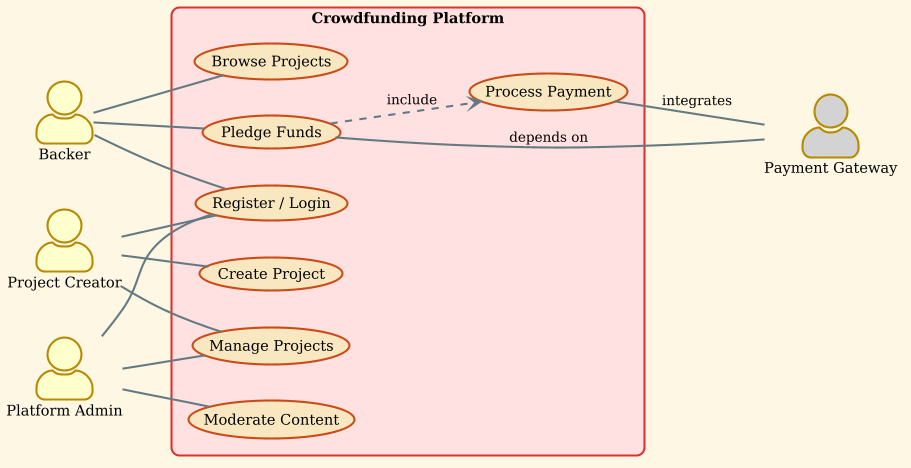
In this model, we represent the System as a rectangular boundary. Inside this boundary lie the Use Cases, which are the specific functions or services the system provides (e.g., “Pledge Funds”). Outside the boundary are the Actors, representing human users or external systems that initiate these functions. The lines connecting Actors to Use Cases represent Associations, indicating who can do what. This abstraction helps stakeholders focus on high-level functionality without getting bogged down in implementation details like database schemas or API endpoints.
Target Domain Scope & Scenario
The scope of this diagram is strictly the core interaction layer of a Crowdfunding Platform. We are modeling the finance industry use case where trust and transaction integrity are key. The boundary includes registration, project management, and funding. It explicitly excludes internal backend logic (like fraud detection algorithms) or UI design details, focusing instead on the operational capabilities available to the actors.
Key Takeaways & Educational Insights
By completing this tutorial, you will gain:
- Actor Identification: Understanding how to distinguish between internal system roles (Admin) and external dependencies (Payment Gateway).
- Boundary Definition: Learning how to encapsulate system functionality within a
rectanglefor clear scope visualization. - Relationship Semantics: Mastering the difference between direct associations (
--) and dependencies (..>) in financial workflows.
Complete Diagram & Full Source Code
Below is the finished blueprint for the Crowdfunding Platform Use Case Diagram. You can copy the code directly into the VPasCode web editor to see the live rendering immediately.
@startuml
left to right direction
skinparam packageStyle rectangle
!theme sunlust

actor "Backer" as Backer
actor "Project Creator" as Creator
actor "Platform Admin" as Admin
actor "Payment Gateway" as Payment #lightgray

rectangle "Crowdfunding Platform" {
    usecase "Register / Login" as UC1
    usecase "Create Project" as UC2
    usecase "Browse Projects" as UC3
    usecase "Pledge Funds" as UC4
    usecase "Process Payment" as UC5
    usecase "Manage Projects" as UC6
    usecase "Moderate Content" as UC7
}

Backer -- UC1
Backer -- UC3
Backer -- UC4

Creator -- UC1
Creator -- UC2
Creator -- UC6

Admin -- UC1
Admin -- UC6
Admin -- UC7

UC4 -- Payment : depends on
UC5 -- Payment : integrates
UC4 ..> UC5 : include

@endumlStep-by-Step Architectural Walkthrough
Building a professional diagram requires a structured approach. We will construct this model in four distinct phases, starting from the canvas setup to the final relationship mapping.
Phase 1: Canvas Configuration & Layout Directives
The foundation of any PlantUML diagram lies in its configuration directives. These lines control the overall look and feel of the diagram before any actors or use cases are drawn. For a finance application, a clean, professional layout is preferred.
First, we set the direction of the diagram flow:
left to right directionThis ensures the diagram reads horizontally, which is often better for wide system boundaries. Next, we define the skin parameters to style the packages:
skinparam packageStyle rectangleFinally, we apply the sunlust theme, which provides a modern, vibrant color palette suitable for web-based tools:
!theme sunlustPhase 2: Declaring Core Entities, Actors, and Boundaries
With the canvas ready, we declare the participants. In a Use Case Diagram, Actors are external to the system. We define them using the actor keyword. Note how we assign an alias (e.g., as Backer) to reference them later without repeating long strings.
actor "Backer" as Backer
actor "Project Creator" as Creator
actor "Platform Admin" as Admin
actor "Payment Gateway" as Payment #lightgray
We also define the system boundary using a rectangle. Everything inside this block belongs to the Crowdfunding Platform:
rectangle "Crowdfunding Platform" {
    // Use cases go here
}
Phase 3: Mapping Data Flows & Key Interactions
Inside the system boundary, we define the functional goals (Use Cases). We assign them short aliases (UC1, UC2, etc.) for cleaner relationship mapping.
usecase "Register / Login" as UC1
usecase "Pledge Funds" as UC4
usecase "Process Payment" as UC5
Next, we connect the Actors to their respective Use Cases. A solid line (--) indicates a direct association, meaning the actor can perform that action.
Backer -- UC1
Backer -- UC3
Backer -- UC4
We repeat this for the Creator and Admin, ensuring their specific permissions are mapped correctly.
Phase 4: Grouping, Annotations & Visual Polish
The final phase involves complex relationships. External integrations, like the Payment Gateway, are often modeled as actors outside the main system boundary but interacting with internal use cases. We use a dashed line (..>) with include to show that “Pledge Funds” requires “Process Payment” to complete.
UC4 ..> UC5 : includeWe also add dependency labels to clarify the nature of the interaction with external systems:
UC4 -- Payment : depends on
UC5 -- Payment : integrates
Syntax & Keyword Deep Dive
Understanding the specific PlantUML syntax is key to mastering VPasCode. Here is a breakdown of the keywords used in this Crowdfunding Platform diagram:
actor: Defines an external entity (human or system) that interacts with the system. Aliases likeas Backerare mandatory for referencing.rectangle: Creates a system boundary. All use cases inside are considered part of the internal system logic.usecase: Defines a specific function or service provided by the system. Aliases allow for cleaner connection lines.--: Represents a solid association line, indicating a direct relationship between an actor and a use case...>: Represents a dashed arrow, often used forincludeorextendrelationships to show dependency flows.!theme: A VPasCode directive to apply a specific visual theme (e.g.,sunlust) to the rendered diagram.
Best Practices & Pitfalls to Avoid
To maintain high-quality documentation, follow these architectural modeling best practices:
- Keep Abstraction Levels Consistent: Do not mix high-level business goals (“Register”) with low-level technical tasks (“Validate Email Token”). Keep the diagram focused on user-facing functionality.
- Use Clear Naming Conventions: Always use the
asalias to create short, unique identifiers (e.g.,as UC1) for use cases. This prevents cluttered lines in the final render. - Manage External Dependencies: Treat external systems (like Payment Gateways) as actors. This clarifies that the platform relies on an external service for specific outcomes.
- Validate Relationships: Ensure every actor has a purpose. If an actor has no lines connecting to the system, they are likely unnecessary in this context.
Start Building PlantUML Diagrams Faster with VPasCode
Test, preview, and customize your Crowdfunding Platform Use Case diagram instantly in your browser with zero installation required.