


Introduction: Visualizing Security Architectures
In the realm of educational technology and campus infrastructure, security is paramount. Whether managing physical entry to laboratories or digital access to learning management systems, architects must clearly define how different user roles interact with the system. A Use Case Diagram serves as the blueprint for these interactions, mapping out the functional requirements from the perspective of external entities. By leveraging diagram-as-code tools like VPasCode, software architects can rapidly prototype these security models with precision, ensuring that every actor and system boundary is explicitly defined before a single line of backend code is written.

This tutorial demonstrates how to build a professional Campus Access Control System diagram using PlantUML within the VPasCode editor. We will explore how to organize primary and secondary actors, define the system boundary, and model complex relationships such as extensions, all while maintaining a clean, maintainable codebase.
Understanding the Model: Purpose, Scope & Problem Framing
Before diving into the syntax, it is essential to understand the architectural abstraction we are modeling.
Diagram Abstraction & Representation
A Use Case Diagram is not merely a flowchart; it is a functional requirement specification. In this model, actors represent the distinct roles (Students, Faculty, Security) that initiate actions within the system. Use Cases represent the high-level goals or services provided by the system (e.g., “Grant Access”). The system boundary (the rectangle) encapsulates the functionality owned by the system itself, distinguishing between internal logic and external interaction.
Target Domain Scope & Scenario
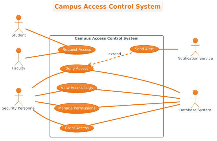
This diagram specifically models the Campus Access Control System. The scope is limited to the core functionality of granting, denying, and logging access permissions. It intentionally excludes peripheral systems like the physical card reader hardware or the network infrastructure, focusing instead on the logical interaction between the user roles and the access control logic. Secondary actors like the Database System and Notification Service are included to show dependencies for data persistence and alerting.
Key Takeaways & Educational Insights
By completing this masterclass, you will gain the ability to:
- Define clear system boundaries to separate concerns.
- Differentiate between primary user interactions and backend service dependencies.
- Utilize PlantUML extensions (like `extend`) to model optional behaviors without cluttering the main flow.
Complete Diagram & Full Source Code
Below is the finished blueprint for the Campus Access Control System. You can view the rendered result below and use the interactive editor to modify the code.
Copy the complete source code below to replicate this diagram in VPasCode:
@startuml
!theme aws-orange

title Campus Access Control System

/'
This diagram illustrates the use cases for a Campus Access Control System.
The system manages entry and exit permissions for various campus facilities.
Primary actors include Students, Faculty, and Security Personnel who interact
with the system to gain access or manage access controls. Secondary actors
include the Database System and Notification Service that support the core
functionality by storing access records and sending alerts when necessary.
'/

left to right direction

actor Student
actor Faculty
actor "Security Personnel" as Security

rectangle "Campus Access Control System" {
    usecase "Request Access" as UC1
    usecase "Grant Access" as UC2
    usecase "Deny Access" as UC3
    usecase "View Access Logs" as UC4
    usecase "Manage Permissions" as UC5
    usecase "Send Alert" as UC6
}

actor "Database System" as DB
actor "Notification Service" as NS

Student -- UC1
Faculty -- UC1
Security -- UC2
Security -- UC3
Security -- UC4
Security -- UC5

UC2 --- DB
UC3 --- DB
UC4 --- DB
UC5 --- DB

UC3 <.. UC6 : extend
UC6 -- NS

@endumlStep-by-Step Architectural Walkthrough
Follow these phases to construct the diagram from scratch, ensuring each component is logically placed and syntactically correct.
Phase 1: Canvas Configuration & Layout Directives
Every PlantUML diagram begins with initialization commands. We start by setting the theme to match the VPasCode aesthetic and defining the diagram title. This establishes the visual identity immediately.
Next, we define the reading direction. For use case diagrams, a horizontal flow often represents the logical progression from user to system.
!theme aws-orange
title Campus Access Control System

left to right direction
We also include a comment block to document the context. This is crucial for living documentation, allowing future developers to understand the diagram’s intent without reading the code logic.
/'
This diagram illustrates the use cases for a Campus Access Control System.
... (full comment text)
'/
Phase 2: Declaring Core Entities, Actors, and Boundaries
Once the canvas is ready, we declare the actors. Actors represent the external entities interacting with the system. We group the primary actors (Students, Faculty, Security) outside the system boundary.
actor Student
actor Faculty
actor "Security Personnel" as Security
The system boundary is defined using the rectangle keyword. This visually separates the system’s internal logic from the external world. Inside this boundary, we define the use cases.
rectangle "Campus Access Control System" {
    usecase "Request Access" as UC1
    usecase "Grant Access" as UC2
    ...
}
Phase 3: Mapping Data Flows & Key Interactions
Now we connect the actors to the use cases. In PlantUML, the association is denoted by --. Notice how we connect the primary actors (Student, Faculty) to the entry point (UC1), and Security Personnel to the management functions (UC2, UC3, UC4, UC5).
Student -- UC1
Faculty -- UC1
Security -- UC2
We also connect secondary actors (DB, NS) to the use cases that require their services. These represent backend dependencies rather than direct user actions.
UC2 --- DB
UC3 --- DB
UC6 -- NS
Phase 4: Grouping, Annotations & Visual Polish
Finally, we model complex relationships. The extend relationship is used here to show that “Send Alert” (UC6) is an optional behavior triggered by “Deny Access” (UC3). This keeps the main flow clean while acknowledging error handling paths.
UC3 <.. UC6 : extendThis phase ensures the diagram is not just a list of connections, but a representation of the system’s behavioral logic.
Syntax & Keyword Deep Dive
Understanding the specific PlantUML syntax is key to mastering diagram-as-code. Here are the critical keywords used in this tutorial:
@startuml: Marks the beginning of a PlantUML diagram. It tells the parser to start interpreting the following lines as diagram code.!theme: Applies a predefined visual theme. In this case,aws-orangeprovides a modern, high-contrast look suitable for professional documentation.actor: Declares a participant in the system. It can be followed by a name or a label. Aliases (e.g.,as Security) help keep code concise.rectangle: Creates a boundary box. Anything inside this block is considered part of the system being modeled.usecase: Defines a specific function or goal within the system boundary. Using aliases (e.g.,as UC1) allows for cleaner connection syntax.--: Represents a standard association (relationship) between an actor and a use case, or between two components.<..: Represents a directed relationship, often used forextendorincluderelationships to show dependency flow./'and'/: Used to wrap multi-line comments. This text is rendered in the diagram description but does not affect the rendering logic.
Best Practices & Pitfalls to Avoid
To maintain high-quality diagrams in VPasCode, adhere to these modeling guidelines:
- Keep Diagrams Modular: Do not attempt to model the entire enterprise in a single file. Split diagrams by subsystem (e.g., “Access Control” vs. “User Management”).
- Consistent Naming Conventions: Use aliases consistently (e.g.,
as UC1) to make connection lines readable and maintainable. - Avoid Visual Clutter: Limit the number of actors and use cases per diagram. If the diagram becomes too dense, consider breaking it down into sub-diagrams.
- Document Context: Always use the comment block (
/') to explain the diagram’s purpose. Code explains syntax; comments explain architecture.
Try It Yourself with VPasCode
Master Campus Access Control System Modeling with VPasCode
Instantly render, customize, and export your Campus Access Control System use case diagram directly in your browser with zero setup.