


In the rapidly evolving fintech sector, clarity in system requirements is paramount. A Cryptocurrency Exchange System is a complex architecture involving sensitive financial transactions, external regulatory compliance, and high-frequency trading logic. For software architects and product managers, visualizing these interactions before writing a single line of application code is critical to preventing scope creep and ensuring security compliance.

Diagramming-as-code offers a modern solution to this challenge. By using PlantUML within VPasCode, teams can define system boundaries, actor roles, and functional goals in a text-based format that renders instantly in the browser. This approach enhances architectural clarity, enables rapid visual prototyping, and serves as living technical documentation that stays synchronized with the codebase. In this masterclass, we will construct a comprehensive Use Case diagram for a Cryptocurrency Exchange System, demonstrating how to map internal user actions against external dependencies like Banking Gateways and Blockchain Networks.
Understanding the Model: Purpose, Scope & Problem Framing
Diagram Abstraction & Representation
A Use Case diagram is the ideal tool for defining the functional scope of a system from the perspective of its users. Unlike flowcharts that detail the logic of a process, a Use Case diagram focuses on who does what. It models the interaction between Actors (users or external systems) and Use Cases (functional goals or services provided by the system). In the context of a financial exchange, this abstraction helps stakeholders identify which user roles require specific permissions and which external services the system must integrate with to function correctly.
Target Domain Scope & Scenario
This diagram models the core functional boundaries of a Cryptocurrency Exchange System. The scope includes:
- Internal Actors: Unregistered users, Registered Traders, and System Administrators.
- External Actors: Banking Gateways, Blockchain Networks, and KYC Providers.
- System Functions: Account management, trading operations, fund handling, and regulatory compliance.
Dependencies outside the system boundary (such as the Blockchain or Bank) are modeled as external actors to highlight integration points without cluttering the internal logic.
Key Takeaways & Educational Insights
By building this model, you will gain:
- Boundary Clarity: Distinguish clearly between system-internal logic and external dependencies.
- Role-Based Access Control (RBAC): Visualize which functions are restricted to specific user tiers (e.g., Admin vs. Trader).
- Integration Mapping: Identify critical third-party services (KYC, Blockchain) that require API stability.
Complete Diagram & Full Source Code
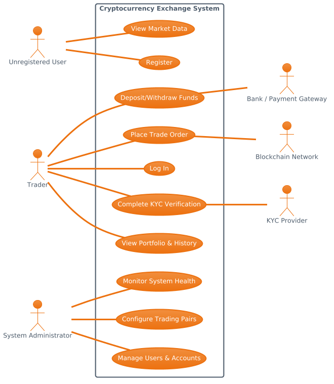
Below is the finished blueprint for the Cryptocurrency Exchange Use Case diagram. You can view the rendered output directly in the interactive editor.
@startuml
!theme aws-orange
left to right direction
skinparam packageStyle rectangle

' Primary Actors (Left)
actor "Unregistered User" as Guest
actor "Trader" as Trader

' Secondary Actors (Right)
actor "Bank / Payment Gateway" as Bank
actor "Blockchain Network" as Blockchain
actor "KYC Provider" as KYC
actor "System Administrator" as Admin

rectangle "Cryptocurrency Exchange System" {
    usecase "Register" as UC1
    usecase "View Market Data" as UC2
    usecase "Log In" as UC3
    usecase "Deposit/Withdraw Funds" as UC4
    usecase "Place Trade Order" as UC5
    usecase "View Portfolio & History" as UC6
    usecase "Complete KYC Verification" as UC7

    usecase "Manage Users & Accounts" as UC8
    usecase "Configure Trading Pairs" as UC9
    usecase "Monitor System Health" as UC10
}

Guest -- UC1
Guest -- UC2
Trader -- UC3
Trader -- UC4
Trader -- UC5
Trader -- UC6
Trader -- UC7

Admin -- UC8
Admin -- UC9
Admin -- UC10

UC4 -- Bank
UC5 -- Blockchain
UC7 -- KYC

@endumlStep-by-Step Architectural Walkthrough
Let’s deconstruct the construction of this diagram into four logical phases. We will build the foundation, define the actors, map the system functions, and finally establish the relationships.
Phase 1: Canvas Configuration & Layout Directives
Before defining entities, we must set the visual theme and layout direction. This ensures consistency with the branding and readability of the diagram.
- Theme Selection: We apply the
aws-orangetheme to give the diagram a professional, financial-tech aesthetic. - Direction: Using
left to right directionaligns the actors logically, with internal users on the left and external systems on the right. - Package Style:
skinparam packageStyle rectangleensures the system boundary is drawn as a solid rectangle.
!theme aws-orange
left to right direction
skinparam packageStyle rectangle
Phase 2: Declaring Core Entities, Actors, and Boundaries
Next, we define the participants. In VPasCode, we use the actor keyword to represent human or system roles. We separate them into Primary Actors (users interacting directly) and Secondary Actors (external dependencies).
' Primary Actors (Left)
actor "Unregistered User" as Guest
actor "Trader" as Trader

' Secondary Actors (Right)
actor "Bank / Payment Gateway" as Bank
actor "Blockchain Network" as Blockchain
actor "KYC Provider" as KYC
actor "System Administrator" as Admin
We then encapsulate the system functionality within a rectangle package. This visually separates what is inside the application from what is outside.
rectangle "Cryptocurrency Exchange System" {
    usecase "Register" as UC1
    usecase "View Market Data" as UC2
    usecase "Log In" as UC3
    usecase "Deposit/Withdraw Funds" as UC4
    usecase "Place Trade Order" as UC5
    usecase "View Portfolio & History" as UC6
    usecase "Complete KYC Verification" as UC7

    usecase "Manage Users & Accounts" as UC8
    usecase "Configure Trading Pairs" as UC9
    usecase "Monitor System Health" as UC10
}
Phase 3: Mapping Data Flows & Key Interactions
Now we connect the actors to the use cases they perform. In PlantUML, the -- symbol denotes a standard association relationship.
- Guest: Can Register and View Market Data.
- Trader: Has broader access including Login, Trading, and KYC.
- Admin: Handles backend management and monitoring.
Guest -- UC1
Guest -- UC2
Trader -- UC3
Trader -- UC4
Trader -- UC5
Trader -- UC6
Trader -- UC7

Admin -- UC8
Admin -- UC9
Admin -- UC10
Phase 4: Grouping, Annotations & Visual Polish
Finally, we map the system’s interaction with external dependencies. This is crucial for understanding API contracts and third-party integrations.
- Funds (UC4): Connects to the
Bank. - Trading (UC5): Connects to the
Blockchain. - Compliance (UC7): Connects to the
KYCprovider.
UC4 -- Bank
UC5 -- Blockchain
UC7 -- KYC
Syntax & Keyword Deep Dive
Understanding the specific PlantUML syntax used in this diagram is essential for adapting it to other financial models.
actor: Defines a participant. The format isactor "Name" as ID.usecase: Defines a functional goal. The format isusecase "Name" as ID.rectangle: Creates a boundary box (package) to group related use cases.--: Represents a standard association line connecting an actor to a use case or a use case to an external actor.!theme: Applies a predefined visual style to the entire diagram.
Best Practices & Pitfalls to Avoid
To ensure your Use Case diagrams remain maintainable and clear, follow these guidelines:
- Keep Use Cases Atomic: Each use case should represent a single goal (e.g., “Place Trade Order” rather than “Trade and Withdraw”).
- Define Boundaries Clearly: Always use a
rectangleorpackageto clearly distinguish system functions from external actors. - Use Descriptive Labels: Avoid abbreviations like “UC1” in the final output labels; use them only for internal ID references.
- Limit Complexity: If a diagram becomes too crowded, split it into subsystem views (e.g., one for Trading, one for Compliance).
Start Building Use Case Diagrams Faster with VPasCode
Visualize your system requirements instantly with VPasCode, the free PlantUML editor for interactive testing and live preview.