


In the telecommunications industry, the provisioning of SIM cards represents a critical operational workflow that bridges customer service, inventory management, and network activation. For architects and software engineers, visualizing this process is not merely about documentation; it is about ensuring data integrity across multiple systems. When a customer requests a new line, the CRM must validate their eligibility, check inventory availability, reserve a specific ICCID, and trigger the network activation gateway. Without a clear visual model, the complexity of these synchronous and asynchronous interactions can lead to race conditions, inventory mismatches, or failed activations.

Sequence diagrams are the ideal tool for mapping these temporal interactions. They allow you to define the precise order of messages exchanged between actors and system components, highlighting the lifecycle of a single request from initiation to completion. By using PlantUML within VPasCode, you can leverage a diagram-as-code approach to define these flows with precision, version them alongside your codebase, and instantly render professional-grade visuals without the drag-and-drop friction of traditional tools.
Understanding the Model: Purpose, Scope & Problem Framing
This tutorial focuses on constructing a Sequence Diagram that models the SIM Card Provisioning Scenario within a CRM (Customer Relationship Management) ecosystem. Unlike a simple flowchart, a sequence diagram captures the time dimension of system interactions. It answers critical architectural questions: Who initiates the request? Which services are involved in the decision-making process? How does the system handle failure states like out-of-stock inventory or network timeouts?
Diagram Abstraction & Representation
In this model, we represent Actors (e.g., Customer) as external entities initiating the process. Participants (e.g., CRM System, Provisioning Engine) represent internal software services or modules. Databases (e.g., SIM Database, Order Database) represent persistent storage layers. The vertical lines (lifelines) represent the existence of these entities over time, while horizontal arrows represent the message passing or method calls between them.
Target Domain Scope & Scenario
We are modeling the end-to-end provisioning lifecycle. This includes the initial customer request, the critical inventory check (to prevent overselling), the reservation of a unique ICCID (Integrated Circuit Card Identifier), and the final activation on the network. Crucially, we also model Alternative Flows using combined fragments, such as what happens if inventory is empty or if the activation gateway times out and requires a retry mechanism.
Key Takeaways & Educational Insights
By completing this tutorial, you will learn how to structure complex conditional logic using alt and else blocks, how to manage activation states with activate and deactivate frames, and how to annotate diagrams with notes and comments for better maintainability.
Complete Diagram & Full Source Code
Before diving into the construction phases, review the complete blueprint below. This diagram encapsulates the entire provisioning logic, including the retry mechanisms and audit trails required for a production-grade telecom system.
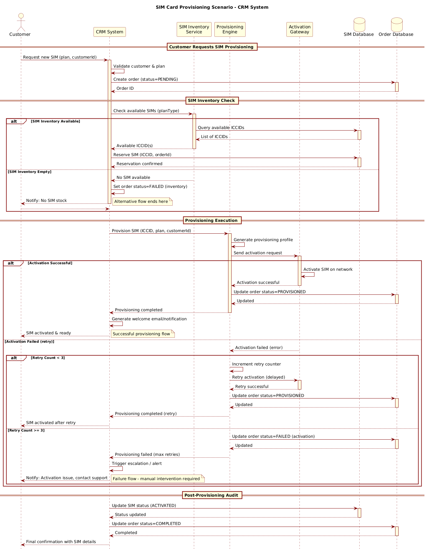
@startuml
!include https://static.visual-paradigm.com/web/resources/plantuml-stdlib/themes/rose.puml

title SIM Card Provisioning Scenario - CRM System

/'
  This sequence diagram illustrates the SIM card provisioning process within a CRM system.
  It covers the end-to-end flow from customer request submission to SIM activation.
  Alternative flows include:
  - SIM inventory availability check
  - Automatic vs. manual assignment of ICCID
  - Success vs. failure handling with retry mechanisms
'/

actor Customer as cust
participant "CRM System" as crm
participant "SIM Inventory\nService" as simInv
participant "Provisioning\nEngine" as provEng
participant "Activation\nGateway" as actGw
database "SIM Database" as simDb
database "Order Database" as orderDb

== Customer Requests SIM Provisioning ==
cust -> crm: Request new SIM (plan, customerId)
activate crm

crm -> crm: Validate customer & plan
crm -> orderDb: Create order (status=PENDING)
activate orderDb
orderDb --> crm: Order ID
deactivate orderDb

== SIM Inventory Check ==
crm -> simInv: Check available SIMs (planType)
activate simInv

alt SIM Inventory Available
    simInv -> simDb: Query available ICCIDs
    activate simDb
    simDb --> simInv: List of ICCIDs
    deactivate simDb
    simInv --> crm: Available ICCID(s)
    deactivate simInv

    crm -> simDb: Reserve SIM (ICCID, orderId)
    activate simDb
    simDb --> crm: Reservation confirmed
    deactivate simDb

else SIM Inventory Empty
    simInv --> crm: No SIM available
    deactivate simInv
    crm -> crm: Set order status=FAILED (inventory)
    crm --> cust: Notify: No SIM stock
    note right: Alternative flow ends here
    deactivate crm
    return
end

== Provisioning Execution ==
crm -> provEng: Provision SIM (ICCID, plan, customerId)
activate provEng

provEng -> provEng: Generate provisioning profile
provEng -> actGw: Send activation request
activate actGw

alt Activation Successful
    actGw -> actGw: Activate SIM on network
    actGw --> provEng: Activation successful
    deactivate actGw
    provEng -> orderDb: Update order status=PROVISIONED
    activate orderDb
    orderDb --> provEng: Updated
    deactivate orderDb
    provEng --> crm: Provisioning completed
    deactivate provEng

    crm -> crm: Generate welcome email/notification
    crm --> cust: SIM activated & ready
    note right: Successful provisioning flow

else Activation Failed (retry)
    actGw --> provEng: Activation failed (error)
    deactivate actGw

    alt Retry Count < 3
        provEng -> provEng: Increment retry counter
        provEng -> actGw: Retry activation (delayed)
        activate actGw
        actGw --> provEng: Retry successful
        deactivate actGw
        provEng -> orderDb: Update order status=PROVISIONED
        activate orderDb
        orderDb --> provEng: Updated
        deactivate orderDb
        provEng --> crm: Provisioning completed (retry)
        deactivate provEng
        crm --> cust: SIM activated after retry
    else Retry Count >= 3
        provEng -> orderDb: Update order status=FAILED (activation)
        activate orderDb
        orderDb --> provEng: Updated
        deactivate orderDb
        provEng --> crm: Provisioning failed (max retries)
        deactivate provEng
        crm -> crm: Trigger escalation / alert
        crm --> cust: Notify: Activation issue, contact support
        note right: Failure flow - manual intervention required
    end
end

deactivate crm

== Post-Provisioning Audit ==
crm -> simDb: Update SIM status (ACTIVATED)
activate simDb
simDb --> crm: Status updated
deactivate simDb

crm -> orderDb: Update order status=COMPLETED
activate orderDb
orderDb --> crm: Completed
deactivate orderDb

crm --> cust: Final confirmation with SIM details
@endumlStep-by-Step Architectural Walkthrough
Building a robust sequence diagram requires a structured approach. We will break the construction down into four distinct phases, moving from global configuration to specific interaction logic.
Phase 1: Canvas Configuration & Layout Directives
Every PlantUML diagram begins with setup directives that define the visual theme and metadata. In VPasCode, you can instantly preview how these directives affect the rendering.
First, we include the rose.puml theme to give the diagram a professional, polished look with soft gradients and rounded borders. This is done using the !include directive:
!include https://static.visual-paradigm.com/web/resources/plantuml-stdlib/themes/rose.puml
Next, we define the title of the diagram. This appears at the top of the rendered output and is crucial for documentation contexts:
title SIM Card Provisioning Scenario - CRM System
We also add a comment block to document the diagram’s scope. PlantUML supports multi-line comments using /' at the start and '/ at the end:
/'
  This sequence diagram illustrates the SIM card provisioning process within a CRM system.
  It covers the end-to-end flow from customer request submission to SIM activation.
  Alternative flows include:
  - SIM inventory availability check
  - Automatic vs. manual assignment of ICCID
  - Success vs. failure handling with retry mechanisms
'/
Phase 2: Declaring Core Entities, Actors, and Boundaries
Before defining messages, we must declare the lifelines. In PlantUML, different types of entities are declared with specific keywords to distinguish their roles.
We start with the Actor, representing the human user:
actor Customer as cust
Next, we define the Participants (services) and Databases. Using participant for services and database for storage helps the renderer apply appropriate icons and styling automatically:
participant "CRM System" as crm
participant "SIM Inventory\nService" as simInv
participant "Provisioning\nEngine" as provEng
participant "Activation\nGateway" as actGw
database "SIM Database" as simDb
database "Order Database" as orderDb
Note the use of \n to force a line break in the label (e.g., “SIM Inventory\nService”). This keeps the diagram clean when names are long.
Phase 3: Mapping Data Flows & Key Interactions
Now we define the actual logic. We group interactions into sections using == headers to improve readability. The core of the provisioning logic relies on alt (alternative) blocks to handle conditional flows.
For the inventory check, we use an alt block to separate the success path from the failure path:
alt SIM Inventory Available
    simInv -> simDb: Query available ICCIDs
    activate simDb
    simDb --> simInv: List of ICCIDs
    deactivate simDb
    simInv --> crm: Available ICCID(s)
    deactivate simInv

    crm -> simDb: Reserve SIM (ICCID, orderId)
    activate simDb
    simDb --> crm: Reservation confirmed
    deactivate simDb

else SIM Inventory Empty
    simInv --> crm: No SIM available
    deactivate simInv
    crm -> crm: Set order status=FAILED (inventory)
    crm --> cust: Notify: No SIM stock
    note right: Alternative flow ends here
    deactivate crm
    return
end
Within these blocks, we use activate and deactivate to show when a participant is busy processing a request. This visualizes the “activation bar” on the lifeline. We also use return to explicitly end the interaction flow for that branch.
Phase 4: Grouping, Annotations & Visual Polish
Finally, we handle the post-provisioning audit and add annotations. Notes are critical for explaining complex logic without cluttering the message arrows.
For the retry logic, we nest another alt block inside the else Activation Failed branch to check the retry count:
alt Retry Count < 3
    provEng -> provEng: Increment retry counter
    provEng -> actGw: Retry activation (delayed)
    activate actGw
    actGw --> provEng: Retry successful
    deactivate actGw
    ...
else Retry Count >= 3
    provEng -> orderDb: Update order status=FAILED (activation)
    ...
end
This nested structure ensures the diagram accurately reflects the business rule: “Retry up to 3 times before escalating to manual intervention.”
Syntax & Keyword Deep Dive
To master PlantUML sequence diagrams, you must understand the specific keywords used to control flow and appearance. Here is a breakdown of the critical syntax features used in this SIM provisioning diagram:
actor: Declares an external human or system actor that initiates the process. In our case,Customer.participant: Declares a system component, service, or module. It renders as a standard rectangle. Used forCRM System,Provisioning Engine, etc.database: Declares a data store. It renders with a cylinder icon to distinguish it from application logic. Used forSIM DatabaseandOrder Database.-->(Arrow): Represents a synchronous message call. The arrow is solid, indicating the sender waits for a response. Used forcust -> crm.-->(Dashed Arrow): Represents a return message or asynchronous response. Used fororderDb --> crm.activate/deactivate: Explicitly control the vertical activation bar on a lifeline. While often implicit, explicit usage ensures clarity in complex nested flows.alt/else/end: Defines combined fragments for alternative logic.altstarts the condition,elsedefines the fallback, andendcloses the block.note right: Adds an annotation to the right of a lifeline or message. Essential for explaining business rules like “Alternative flow ends here”.
Best Practices & Pitfalls to Avoid
When creating sequence diagrams for complex telecom workflows, adherence to best practices ensures your documentation remains maintainable and readable.
1. Modularize with Section Headers
Never write a single continuous block of messages. Use == Section Title == to break the diagram into logical phases (e.g., Inventory Check, Provisioning, Audit). This helps stakeholders quickly locate specific parts of the flow.
2. Manage Visual Complexity with Nested Alt Blocks
It is tempting to flatten all error handling into one long list of messages. Instead, nest your alt blocks. For example, put the retry logic inside the else Activation Failed block. This visually groups related failure scenarios.
3. Use Descriptive Labels for Lifelines
Avoid generic names like Service1. Use domain-specific names like Activation Gateway or SIM Inventory Service. If names are long, use \n to wrap text within the box to maintain a clean width.
4. Explicitly Model Failure Paths
A common pitfall is only modeling the “Happy Path.” In telecom, failure is frequent. Always model the else branches for inventory shortages, network timeouts, and database errors to ensure the diagram reflects reality.
Start Building PlantUML Sequence Diagrams Faster with VPasCode
Instantly render and customize your SIM provisioning workflows in the browser with zero local installation required.