


In the high-stakes environment of financial auditing, clarity is not just a design preference; it is a regulatory necessity. Audit systems must navigate complex webs of regulations, document validations, and risk assessments. When processes become convoluted, the risk of compliance failure increases significantly. This is where visual modeling transitions from a nice-to-have to a critical engineering asset.

Activity diagrams provide the perfect lens for mapping these workflows. They allow architects to visualize the sequence of actions, decision points, and parallel processing required in a compliance check. By adopting a diagram-as-code approach using PlantUML within VPasCode, teams can maintain living documentation that evolves alongside the software. This method eliminates the friction of manual drawing tools, ensuring that the visual representation of the audit logic remains accurate, versioned, and instantly accessible to all stakeholders.
VPasCode, the free web-based diagram-as-code editor, empowers financial engineers to prototype these workflows in the browser without installing local dependencies. This article serves as a masterclass on constructing a robust compliance check activity diagram, demonstrating how to leverage swimlanes, conditional logic, and parallel flows to document a secure audit system.
Understanding the Model: Purpose, Scope & Problem Framing
Diagram Abstraction & Representation
An activity diagram in PlantUML is essentially a flowchart that models the dynamic behavior of a system. Unlike static class diagrams, activity diagrams focus on the process. In the context of an Audit System, the diagram abstracts the lifecycle of a compliance check. It breaks down the process into discrete steps, showing how data moves between different actors (swimlanes) and how the system responds to conditions.
The swimlane notation is critical here. It assigns responsibility to specific entities: the Auditor (human), the System (backend infrastructure), and the Compliance Engine (rule processor). This separation ensures that the diagram clearly delineates where human intervention is required versus where automated logic takes over.
Target Domain Scope & Scenario
This model focuses specifically on the Compliance Check Process. It does not cover the entire audit lifecycle, such as initial data ingestion or final report publishing outside the system. Instead, it isolates the core logic: initiating the check, validating documents, running automated rules, scoring risk, and flagging the outcome. The boundaries are set to ensure the diagram remains readable while capturing the critical decision nodes that determine audit outcomes.
Key Takeaways & Educational Insights
By following this guide, you will gain the ability to:
- Model complex financial workflows using standard PlantUML syntax.
- Implement swimlanes to clarify roles and responsibilities.
- Use fork and join nodes to represent parallel processing tasks.
- Apply conditional logic to simulate risk assessment thresholds.
Complete Diagram & Full Source Code
Below is the complete blueprint for the Compliance Check Process. You can view the rendered result immediately by pasting this code into the VPasCode editor.
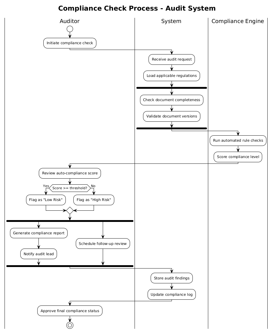
@startuml
!theme plain
title Compliance Check Process - Audit System

|Auditor|
start
:Initiate compliance check;

|System|
:Receive audit request;
:Load applicable regulations;

fork
   :Check document completeness;
   :Validate document versions;
end fork

|Compliance Engine|
:Run automated rule checks;
:Score compliance level;

|Auditor|
:Review auto-compliance score;

if (Score >= threshold?) then (Yes)
   :Flag as "Low Risk";
else (No)
   :Flag as "High Risk";
endif

fork
   :Generate compliance report;
   :Notify audit lead;
fork again
   :Schedule follow-up review;
end fork

|System|
:Store audit findings;
:Update compliance log;

|Auditor|
:Approve final compliance status;

stop
@endumlStep-by-Step Architectural Walkthrough
Building a professional diagram requires a structured approach. We will deconstruct the code into four logical phases to understand how each component contributes to the final architecture.
Phase 1: Canvas Configuration & Layout Directives
Every PlantUML diagram begins with setup directives. These define the global behavior and visual theme of the canvas. In this audit scenario, we want a clean, professional look that prioritizes readability over decorative flair.
We start by declaring the diagram type and theme:
@startuml
!theme plain
title Compliance Check Process - Audit System
The @startuml directive signals the beginning of the diagram. The !theme plain directive applies a minimalist style, removing heavy shadows or gradients that might distract from the logic flow. The title directive provides a clear header for the diagram, which is essential for documentation archives.
Phase 2: Declaring Core Entities, Actors, and Boundaries
Financial systems rely on clear separation of duties. We define this using swimlanes. Each vertical lane represents a distinct actor or subsystem.
We define the lanes using the pipe syntax |Name|:
|Auditor|
start
:Initiate compliance check;

|System|
:Receive audit request;
:Load applicable regulations;
The start node marks the entry point of the workflow. The colon : prefix denotes an activity node. Notice how the flow moves from the Auditor to the System. This visual flow immediately tells the reader who triggers the process and which component handles the initial request.
Phase 3: Mapping Data Flows & Key Interactions
Complex audit processes often involve parallel tasks. We cannot check document completeness and validate versions sequentially if they are independent. Here, we utilize the fork directive to split the flow.
fork
   :Check document completeness;
   :Validate document versions;
end fork
The fork and end fork keywords create a split and a join. This indicates that both tasks must be completed before the process continues to the next stage (the Compliance Engine). This is crucial for modeling concurrency in audit systems where multiple validation checks happen simultaneously.
Phase 4: Grouping, Annotations & Visual Polish
The final phase involves decision logic and concluding the process. We use an if statement to model the risk assessment threshold.
if (Score >= threshold?) then (Yes)
   :Flag as "Low Risk";
else (No)
   :Flag as "High Risk";
endif
This conditional block branches the workflow based on the compliance score. Finally, we use another fork to handle post-processing tasks like report generation and notification, ensuring these happen in parallel. The process concludes with the stop node, indicating the end of the compliance check lifecycle.
Syntax & Keyword Deep Dive
Understanding the specific PlantUML keywords used in this diagram is essential for replicating this pattern in other projects. Below is a breakdown of the core syntax elements.
|Lane|: Defines a swimlane. It groups activities under a specific actor or subsystem, clarifying ownership of tasks.start/stop: Mark the entry and exit points of the activity flow. Every valid activity diagram must have these.fork/end fork: Creates parallel branches. Multipleforkblocks can be nested or chained to manage complex concurrency.if ... then ... else ... endif: Implements decision logic. It allows the diagram to branch based on runtime conditions, such as risk thresholds.title: Sets the main heading of the diagram, useful for embedding in reports.
Best Practices & Pitfalls to Avoid
When modeling financial workflows, precision is key. Follow these best practices to maintain high-quality diagrams.
- Maintain Swimlane Consistency: Do not move an activity node from one lane to another mid-flow unless it represents a handoff. Keep responsibilities clearly separated.
- Limit Fork Depth: While parallel flows are powerful, nesting too many forks can make the diagram unreadable. Keep parallel branches to a maximum of 3-4 tasks per fork.
- Use Descriptive Labels: Avoid generic labels like “Process” or “Check”. Use specific terms like “Validate Document Versions” to ensure the diagram is self-documenting.
- Visual Hierarchy: Use the
!themedirective to ensure consistent styling. In finance, a clean, plain theme often conveys more authority than a colorful one.
Start Building Activity Diagrams Faster with VPasCode
Visualize complex financial audit workflows instantly with live browser preview, zero installation, and interactive syntax testing.