


In the high-stakes environment of financial technology, clarity is not just a design preference—it is a security requirement. When architects design the backend logic for an Automated Teller Machine (ATM), understanding the precise sequence of interactions between hardware components (like card readers) and software services (like PIN validators) is critical. A single misaligned message flow can lead to security vulnerabilities or transaction failures.
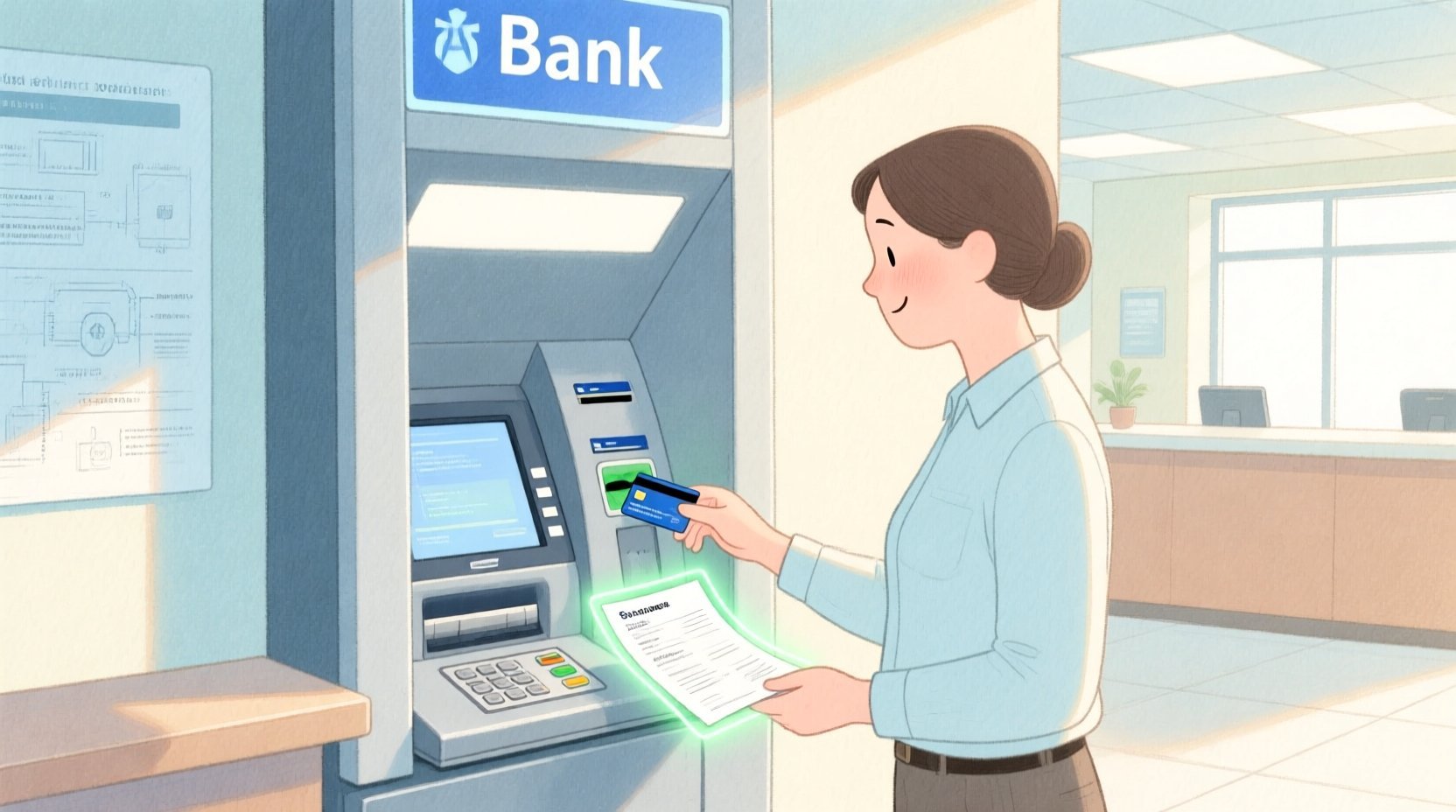
This tutorial demonstrates how to model a Mini Statement Printing scenario within an ATM system using PlantUML. By leveraging VPasCode, our free web-based diagram-as-code editor, architects can rapidly prototype these workflows without configuring local environments. This approach ensures that documentation remains living, versioned, and instantly accessible across teams.
Understanding the Model: Purpose, Scope & Problem Framing
Diagram Abstraction & Representation
A sequence diagram is the ideal tool for modeling time-ordered interactions between objects or actors. In this specific scenario, we are not merely drawing boxes and lines; we are visualizing the temporal flow of a banking transaction. The diagram captures the lifecycle of a request from the moment a customer inserts a card until the final statement is dispensed.
Why Sequence Diagrams? For finance professionals, this notation is superior to static flowcharts because it explicitly shows:
- Temporal Dependencies: Which service must respond before the next step begins.
- Synchronous vs. Asynchronous Calls: Whether the ATM waits for a PIN validation result before proceeding.
- Alternative Flows: How the system handles errors, such as an incorrect PIN, using combined fragments.
Target Domain Scope & Scenario
This model focuses strictly on the Mini Statement workflow. It intentionally excludes other ATM functions like cash withdrawal or balance transfer to maintain architectural clarity. The boundaries include the physical Customer, the ATM Machine logic, peripheral hardware (Card Reader), security validation (PIN Validator), core banking data (Account Service), and the output device (Statement Printer).
Key Takeaways & Educational Insights
By completing this guide, you will gain the ability to:
- Define complex error-handling logic using alt and else blocks.
- Structure lifelines for both human actors and technical participants.
- Apply professional visual themes to enhance documentation quality.
Complete Diagram & Full Source Code
Before diving into the construction, review the complete blueprint. This diagram illustrates a robust flow that accounts for successful transactions and security lockouts.
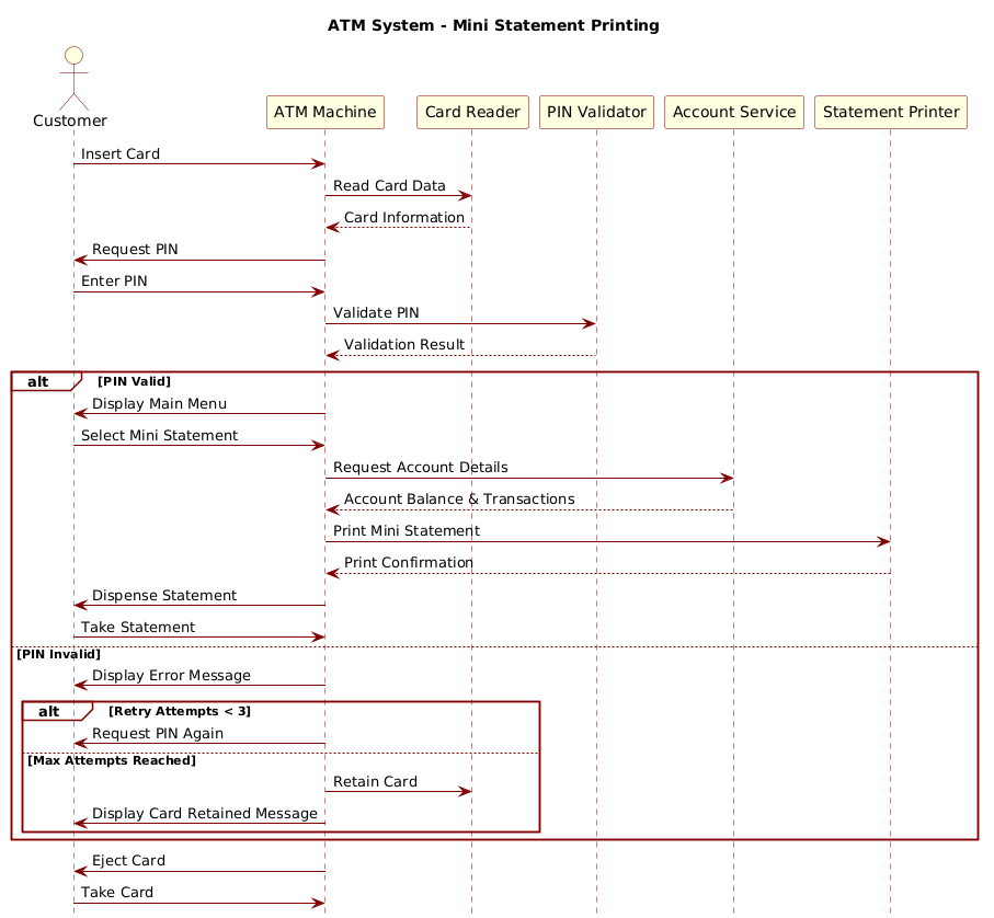
Below is the complete source code required to render this diagram. You can copy this directly into the VPasCode editor.
@startuml
!include https://static.visual-paradigm.com/web/resources/plantuml-stdlib/themes/rose.puml

title ATM System - Mini Statement Printing

actor Customer as customer
participant "ATM Machine" as atm
participant "Card Reader" as cardReader
participant "PIN Validator" as pinValidator
participant "Account Service" as accountService
participant "Statement Printer" as printer

customer -> atm: Insert Card
atm -> cardReader: Read Card Data
cardReader --> atm: Card Information

atm -> customer: Request PIN
customer -> atm: Enter PIN
atm -> pinValidator: Validate PIN
pinValidator --> atm: Validation Result

alt PIN Valid
    atm -> customer: Display Main Menu
    customer -> atm: Select Mini Statement
    atm -> accountService: Request Account Details
    accountService --> atm: Account Balance & Transactions

    atm -> printer: Print Mini Statement
    printer --> atm: Print Confirmation
    atm -> customer: Dispense Statement
    customer -> atm: Take Statement
else PIN Invalid
    atm -> customer: Display Error Message
    alt Retry Attempts < 3
        atm -> customer: Request PIN Again
    else Max Attempts Reached
        atm -> cardReader: Retain Card
        atm -> customer: Display Card Retained Message
    end
end

atm -> customer: Eject Card
customer -> atm: Take Card
@endumlStep-by-Step Architectural Walkthrough
Building a professional sequence diagram involves more than just typing commands. It requires a structured approach to ensure the logic holds up under scrutiny. We will break this down into four phases.
Phase 1: Canvas Configuration & Layout Directives
Every PlantUML diagram begins with setup directives. These define the theme and the overall title, ensuring the diagram looks consistent with your organization’s branding.
First, we include the rose.puml theme. This applies a polished color scheme and styling automatically, saving time on manual skin parameters.
!include https://static.visual-paradigm.com/web/resources/plantuml-stdlib/themes/rose.pumlNext, we define the title directive. This provides context for anyone viewing the diagram without needing to read the surrounding documentation.
title ATM System - Mini Statement PrintingPhase 2: Declaring Core Entities, Actors, and Boundaries
Before drawing connections, we must define the participants. In sequence diagrams, participants are the vertical lifelines that represent the entities exchanging messages.
We distinguish between Actors (human users) and Participants (system components). Using aliases (like as customer) allows us to reference them easily later in the message flow.
actor Customer as customer
participant "ATM Machine" as atm
participant "Card Reader" as cardReader
participant "PIN Validator" as pinValidator
Notice the use of quotes around names containing spaces, such as "ATM Machine". This ensures PlantUML parses the name correctly.
Phase 3: Mapping Data Flows & Key Interactions
This is the core logic of the diagram. We use arrow syntax to denote message passing. A solid arrow (->) indicates a synchronous call where the sender waits for a response, while a dashed arrow (-->) indicates a return message.
We start with the initial trigger: the customer inserts the card.
customer -> atm: Insert Card
atm -> cardReader: Read Card Data
cardReader --> atm: Card Information
We then model the security check. The ATM requests the PIN, the customer enters it, and the system validates it. This creates a clear timeline of the authentication process.
Phase 4: Grouping, Annotations & Visual Polish
Real-world systems rarely follow a single linear path. We must model error handling. The alt block allows us to define alternative flows based on conditions.
In this diagram, we check if the PIN is valid. If not, we enter an else block to handle retries or card retention. Nested alt blocks allow us to check retry attempts within the failure path.
alt PIN Valid
    ... (Success Flow)
else PIN Invalid
    ... (Failure Flow)
end
This structure ensures that the diagram communicates not just the happy path, but also the resilience of the system against incorrect inputs.
Syntax & Keyword Deep Dive
To master PlantUML sequence diagrams, you must understand the specific keywords that drive logic and layout.
actor: Declares a human participant who interacts with the system. In this model, it represents the bank customer.participant: Declares any system component, service, or hardware device that processes data.->(Solid Arrow): Represents a synchronous message call. The sender pauses until the receiver responds.-->(Dashed Arrow): Represents a return message or an asynchronous response flowing back to the sender.alt/else/end: These keywords create combined fragments.altstarts a conditional block,elsedefines the alternative path, andendcloses the block.title: Adds a header to the diagram for immediate identification.
Best Practices & Pitfalls to Avoid
When modeling financial workflows, precision is key. Follow these guidelines to maintain high-quality diagrams.
- Keep Lifelines Vertical: Ensure all participants are declared at the top. Vertical lines make it easier to trace the timeline of events.
- Use Clear Naming: Avoid abbreviations like
atmwithout context. Use descriptive names like"ATM Machine"for clarity. - Limit Complexity per Block: If a sequence becomes too long, consider splitting it into multiple diagrams (e.g., one for Authentication, one for Transaction).
- Validate Logic Early: Use the VPasCode live preview to ensure your
altblocks close correctly. Unclosedendtags are a common syntax error.
Try It Yourself with VPasCode
Start Building Sequence Diagrams Faster with VPasCode
Design complex finance system workflows instantly in your browser with zero setup. Test syntax, preview flows, and export diagrams directly from VPasCode.