


In the modern digital landscape, organizations generate vast quantities of media assets—images, videos, documents, and 3D renders. Managing this digital inventory efficiently requires a robust Digital Asset Management (DAM) system. However, before writing a single line of application code, software architects and product managers must clearly define how users interact with the system. This is where visual modeling becomes indispensable.
A Use Case Diagram serves as the bridge between business requirements and technical implementation. It visually maps out the functional goals of the system and the roles (actors) that achieve them. By using diagram-as-code with PlantUML in VPasCode, teams can rapidly prototype these interactions, ensuring that the system boundary is clear and that no critical user journey is overlooked. This approach transforms abstract requirements into a living, testable blueprint.
Understanding the Model: Purpose, Scope & Problem Framing
Before diving into the syntax, it is crucial to understand what this specific diagram type models and why it is the right visual tool for the Digital Asset Management domain.
Diagram Abstraction & Representation
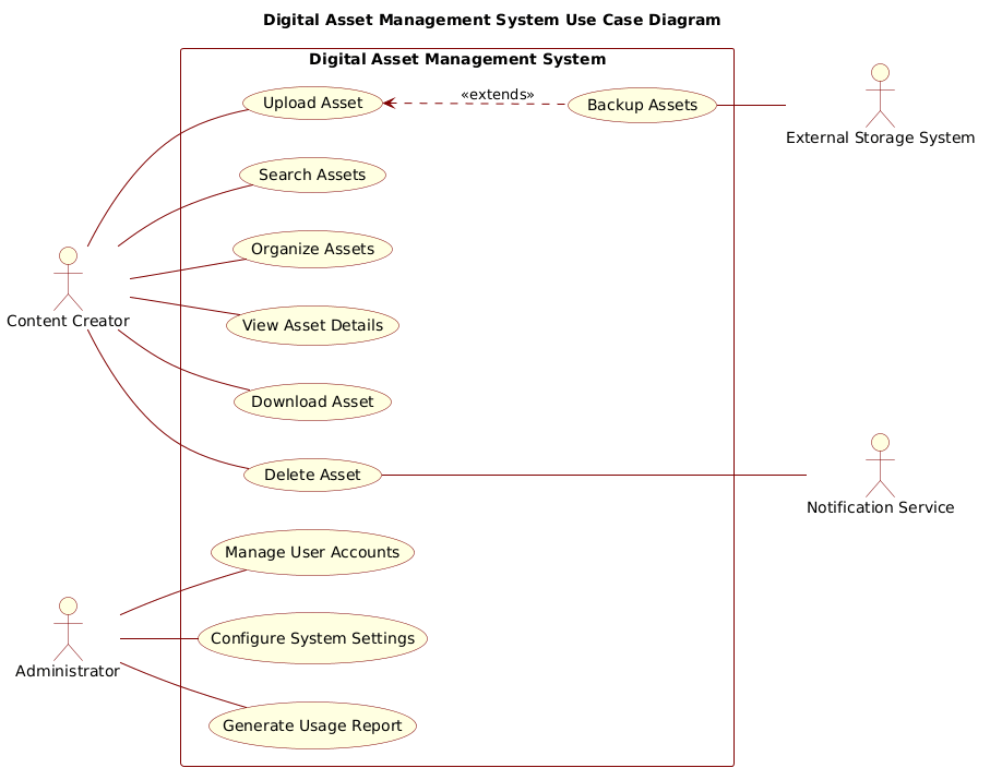
A Use Case Diagram models the functional requirements of a system from the perspective of external users. In this diagram, Actors represent the human roles or external systems interacting with the DAM (such as Content Creators or Administrators). Use Cases represent the specific high-level goals these actors want to achieve, such as uploading an asset or generating a report. The System Boundary (the rectangle) defines the scope of the software being built, separating internal logic from external interaction.
Target Domain Scope & Scenario
This guide focuses on a centralized Digital Asset Management System. The scope includes core asset lifecycle operations: ingestion (upload), discovery (search), organization, and consumption (download/view). It explicitly excludes backend infrastructure details, focusing purely on user-facing functionality. The diagram captures both primary human users (Creators, Admins) and secondary external systems (Storage, Notifications) that support the core workflow.
Key Takeaways & Educational Insights
By building this model, you will gain clarity on:
- Role Separation: Clearly distinguishing between what a Content Creator can do versus an Administrator.
- System Boundaries: Defining exactly which features belong inside the DAM application.
- External Dependencies: Visualizing how the system relies on external services like storage or notification channels.
Complete Diagram & Full Source Code
Below is the finished blueprint for the Digital Asset Management System. This diagram defines the system scope, identifies key actors, and maps out the primary interactions including an extended workflow for asset backup.
@startuml
!include https://static.visual-paradigm.com/web/resources/plantuml-stdlib/themes/rose.puml

title Digital Asset Management System Use Case Diagram
/'
This diagram illustrates the use cases for a Digital Asset Management (DAM) System.
The system enables users to upload, organize, search, and manage digital assets such as
images, videos, documents, and other media files. Primary actors include Content Creators
who upload and manage assets, and Administrators who oversee system configuration and user
management. Secondary actors include External Storage Systems that provide backup and
archival capabilities, and Notification Services that alert users about asset status changes.
'/

left to right direction

actor "Content Creator" as creator
actor "Administrator" as admin

rectangle "Digital Asset Management System" {
    usecase "Upload Asset" as UC1
    usecase "Search Assets" as UC2
    usecase "Organize Assets" as UC3
    usecase "View Asset Details" as UC4
    usecase "Download Asset" as UC5
    usecase "Delete Asset" as UC6
    usecase "Manage User Accounts" as UC7
    usecase "Configure System Settings" as UC8
    usecase "Generate Usage Report" as UC9
    usecase "Backup Assets" as UC10
}

actor "External Storage System" as storage
actor "Notification Service" as notification

creator -- UC1
creator -- UC2
creator -- UC3
creator -- UC4
creator -- UC5
creator -- UC6

admin -- UC7
admin -- UC8
admin -- UC9

UC1 <.. UC10 : <<extends>>
UC10 -- storage
UC6 --- notification

@endumlStep-by-Step Architectural Walkthrough
Now that you have the full picture, let’s deconstruct the code to understand how we built this architecture. We will follow a logical progression from setup to complex relationships.
Phase 1: Canvas Configuration & Layout Directives
Every PlantUML diagram begins with initialization. We start by including a visual theme to give the diagram a professional, consistent look. We also set the layout direction to ensure the diagram flows logically from left to right, which is standard for use case diagrams.
!include https://static.visual-paradigm.com/web/resources/plantuml-stdlib/themes/rose.puml
title Digital Asset Management System Use Case Diagram
left to right direction
The !include directive pulls in the visual style definitions, while the title command sets the main heading. The left to right direction directive ensures that actors appear on the left and use cases on the right, improving readability.
Phase 2: Declaring Core Entities, Actors, and Boundaries
Next, we define the primary actors who interact with the system. We assign them aliases (like creator and admin) to make the code cleaner and easier to reference later. We then define the system boundary using a rectangle.
actor "Content Creator" as creator
actor "Administrator" as admin

rectangle "Digital Asset Management System" {
    // Use cases go here
}
The rectangle block is critical. It visually encapsulates the use cases, clearly distinguishing them from external actors. This boundary tells stakeholders exactly what the software is responsible for versus what exists outside of it.
Phase 3: Mapping Data Flows & Key Interactions
Inside the boundary, we declare the specific use cases. Each use case represents a functional goal. We then connect the primary actors to these use cases using simple association lines.
usecase "Upload Asset" as UC1
usecase "Search Assets" as UC2

creator -- UC1
creator -- UC2
Notice the creator -- UC1 syntax. In PlantUML, the double hyphen -- creates a solid line representing a standard association. This indicates that the Content Creator can perform the “Upload Asset” action.
Phase 4: Grouping, Annotations & Visual Polish
Finally, we handle secondary actors and advanced relationships. Secondary actors like storage and notification interact with the system but are not the primary users. We also add an extend relationship to show optional behavior.
UC1 <.. UC10 : <>
UC10 -- storage
The dotted line <.. combined with the < stereotype indicates that "Backup Assets" is an optional extension of the "Upload Asset" process. This level of detail helps developers understand conditional logic without writing it yet.
Syntax & Keyword Deep Dive
Understanding the specific PlantUML syntax is key to mastering diagram-as-code. Here are the core keywords used in this Digital Asset Management model:
actor: Defines an entity (human or system) that interacts with the use cases. Example:actor "Content Creator".usecase: Defines a functional goal or action within the system. Example:usecase "Search Assets".rectangle: Creates a system boundary box to group related use cases and define scope.--: Represents a standard association (solid line) between an actor and a use case.<..: Represents a directed relationship, often used for extensions or includes.<: A stereotype that indicates one use case adds optional behavior to another (e.g., Backup extends Upload).> /' ... '/: A comment block used to add context or descriptions that do not appear in the rendered diagram.
Best Practices & Pitfalls to Avoid
To ensure your diagrams remain maintainable and clear, follow these architectural guidelines:
- Keep Actors Distinct: Avoid creating too many similar actors. If two actors do the same thing, consider if they should be merged or if the system boundary needs adjustment.
- Use Meaningful Aliases: Just like in programming, use short, unique aliases (e.g.,
admininstead ofAdministrator) for actors and use cases to reduce code length and improve readability. - Define Clear Boundaries: Ensure every use case inside the rectangle is something the system *does*, not something the user *does*. The boundary separates the software from the world.
- Limit Complexity: If a diagram becomes too crowded, consider splitting it into subsystem diagrams. A single diagram should focus on a specific scope, such as the "User Management" scope or the "Asset Ingestion" scope.
Try It Yourself with VPasCode
Start Building PlantUML Diagrams Faster with VPasCode
Instantly visualize your Digital Asset Management architecture with zero setup. Test, preview, and customize your Use Case diagrams directly in your browser.