


In the modern fintech landscape, the customer onboarding process is the critical gateway to financial services. For banks and digital lenders, the “Savings Account Opening” workflow is not merely a form submission; it is a complex orchestration of identity verification, regulatory compliance, and data persistence. Misunderstanding this flow can lead to compliance breaches, customer friction, and operational bottlenecks.
Visual modeling is essential for aligning stakeholders—from backend engineers handling KYC services to product managers designing the online portal. However, traditional drag-and-drop tools often struggle with the complexity of conditional logic (like AML alerts) and state transitions. This is where diagram-as-code shines.
By using PlantUML within VPasCode, architects can define these intricate financial workflows in text, ensuring precision and versioning capability. VPasCode provides an instant browser-based rendering engine, allowing you to iterate on the logic of your sequence diagrams without installing Java or local dependencies. This tutorial serves as a masterclass in modeling a robust, compliant onboarding flow, demonstrating how to structure actors, participants, and combined fragments for alternative business rules.
Understanding the Model: Purpose, Scope & Problem Framing
Diagram Abstraction & Representation
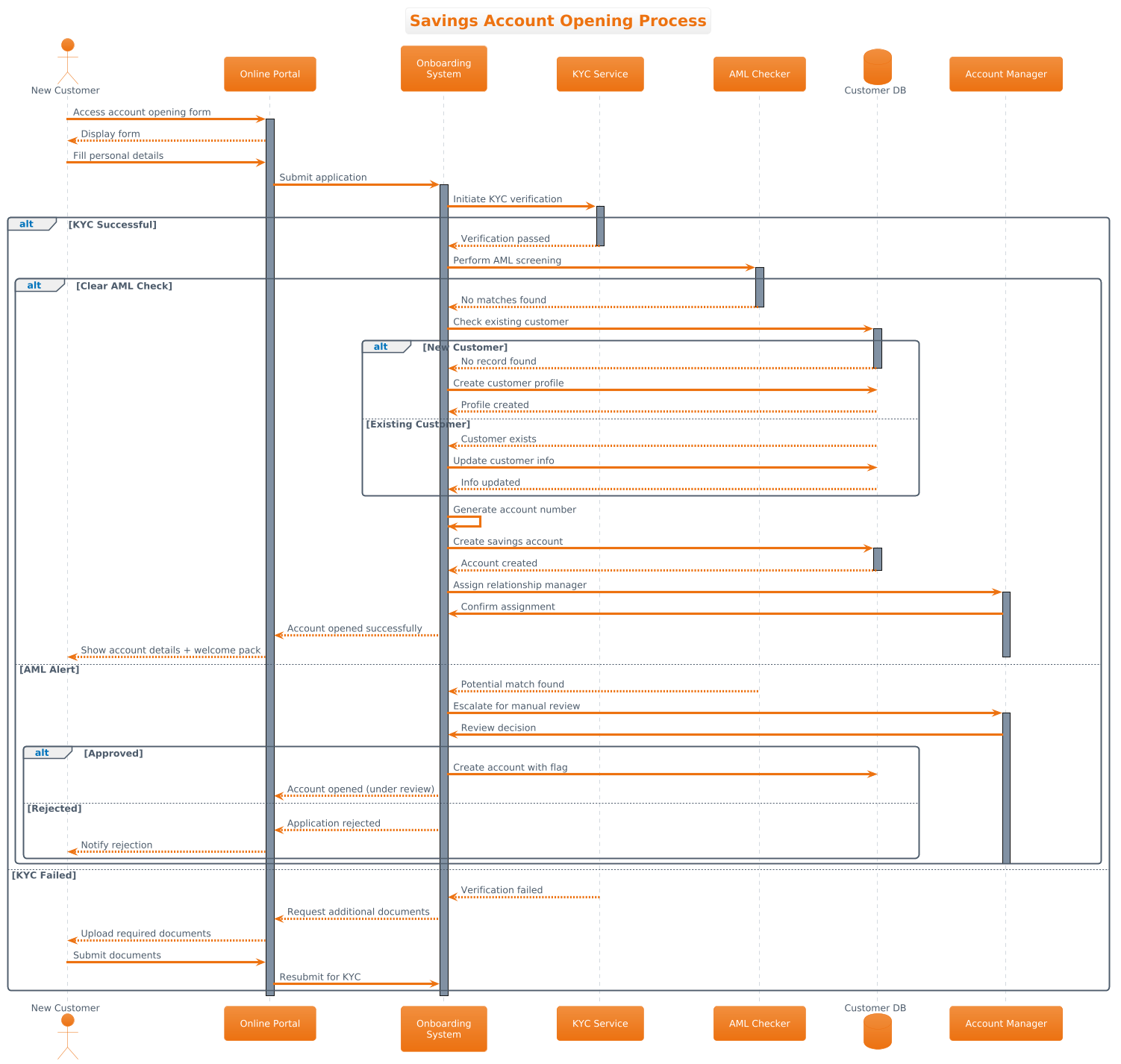
This tutorial focuses on a Sequence Diagram, the standard notation for modeling time-ordered interactions between system components. In a finance context, sequence diagrams are invaluable because they map the temporal flow of data. Unlike a static architecture diagram, a sequence diagram answers the question: “What happens, and in what order, when a customer submits their application?”
We will model the following key abstractions:
- Lifelines: Representing the “New Customer,” the “Online Portal,” the “Onboarding System,” and external services like “KYC” and “AML Checker.”
- Messages: Synchronous calls (solid arrows) for immediate requests (e.g., “Submit Application”) and asynchronous responses (dashed arrows) for feedback.
- Activation Bars: Indicating the period during which a component is actively processing a request, crucial for understanding concurrency and load.
Target Domain Scope & Scenario
The scope of this model is the Customer Onboarding System specifically for opening a Savings Account. It intentionally excludes unrelated processes like loan origination or credit card applications to maintain clarity. The diagram covers the end-to-end journey from the initial form access to the final account creation or rejection.
Key dependencies modeled include:
- Regulatory Compliance: Mandatory checks for Know Your Customer (KYC) and Anti-Money Laundering (AML).
- Data Integrity: Ensuring existing customers are updated rather than duplicated.
- Operational Workflows: Escalation paths to human “Account Managers” for manual review when automated checks fail.
Key Takeaways & Educational Insights
By following this guide, you will gain the ability to:
- Model complex conditional logic using
altblocks for alternative flows. - Manage visual complexity by separating concerns (KYC vs. AML vs. Database).
- Apply professional styling (themes) to match enterprise branding standards.
- Use VPasCode to instantly validate your diagram syntax before deployment.
Complete Diagram & Full Source Code
Below is the complete blueprint for the Savings Account Opening Process. This diagram utilizes the aws-orange theme to provide a clean, professional look suitable for financial documentation.
@startuml
!theme aws-orange

title Savings Account Opening Process

actor "New Customer" as Customer
participant "Online Portal" as Portal
participant "Onboarding\nSystem" as System
participant "KYC Service" as KYC
participant "AML Checker" as AML
database "Customer DB" as CDB
participant "Account Manager" as Manager

Customer -> Portal: Access account opening form
activate Portal
Portal --> Customer: Display form
Customer -> Portal: Fill personal details
Portal -> System: Submit application
activate System

System -> KYC: Initiate KYC verification
activate KYC

alt KYC Successful
    KYC --> System: Verification passed
    deactivate KYC

    System -> AML: Perform AML screening
    activate AML

    alt Clear AML Check
        AML --> System: No matches found
        deactivate AML

        System -> CDB: Check existing customer
        activate CDB

        alt New Customer
            CDB --> System: No record found
            deactivate CDB
            System -> CDB: Create customer profile
            CDB --> System: Profile created
        else Existing Customer
            CDB --> System: Customer exists
            deactivate CDB
            System -> CDB: Update customer info
            CDB --> System: Info updated
        end

        System -> System: Generate account number
        System -> CDB: Create savings account
        activate CDB
        CDB --> System: Account created
        deactivate CDB

        System -> Manager: Assign relationship manager
        activate Manager
        Manager -> System: Confirm assignment
        System --> Portal: Account opened successfully
        Portal --> Customer: Show account details + welcome pack

        deactivate Manager

    else AML Alert
        AML --> System: Potential match found
        deactivate AML
        System -> Manager: Escalate for manual review
        activate Manager
        Manager -> System: Review decision
        alt Approved
            System -> CDB: Create account with flag
            System --> Portal: Account opened (under review)
        else Rejected
            System --> Portal: Application rejected
            Portal --> Customer: Notify rejection
        end
        deactivate Manager
    end

else KYC Failed
    KYC --> System: Verification failed
    deactivate KYC
    System --> Portal: Request additional documents
    Portal --> Customer: Upload required documents
    Customer -> Portal: Submit documents
    Portal -> System: Resubmit for KYC
end

deactivate System
deactivate Portal
@endumlStep-by-Step Architectural Walkthrough
Constructing a sequence diagram of this complexity requires a modular approach. We will break the construction down into four logical phases, mirroring how a software architect would design the system.
Phase 1: Canvas Configuration & Layout Directives
Before defining the actors, we must set the stage. The first few lines of code configure the rendering engine and the visual identity of the diagram.
We start with @startuml to signal the beginning of the PlantUML block. We then apply the !theme aws-orange directive. This automatically applies a specific color palette (orange, white, and dark grays) that aligns with modern enterprise UI standards, saving you from manually defining colors for every box.
@startuml
!theme aws-orange

title Savings Account Opening Process
Finally, the title directive adds a clear header to the diagram, ensuring that anyone viewing the exported image immediately understands the context of the workflow.
Phase 2: Declaring Core Entities, Actors, and Boundaries
Next, we define the participants. In a sequence diagram, participants represent the active elements in the system. We use specific keywords to denote their roles:
actor: Represents a human user. Here, we define the"New Customer". We assign an aliasas Customerto keep subsequent messages concise.participant: Represents software components. We define the"Online Portal"and the core"Onboarding System".database: Represents persistent storage. We define the"Customer DB"to clearly distinguish data storage from application logic.
actor "New Customer" as Customer
participant "Online Portal" as Portal
participant "Onboarding
System" as System
database "Customer DB" as CDB
Note the use of \n within the string to break lines (e.g., in “Onboarding\nSystem”), ensuring the text fits neatly within the participant box.
Phase 3: Mapping Data Flows & Key Interactions
This is the core logic of the diagram. We model the happy path and the exception paths using sequential messages and combined fragments.
The Happy Path: The customer interacts with the portal, which sends a request to the system. The system then initiates verification.
Customer -> Portal: Access account opening form
Portal -> System: Submit application
System -> KYC: Initiate KYC verification
Handling Alternative Flows (alt blocks): In finance, exceptions are common. We use the alt keyword to represent conditional logic. For example, if KYC fails, the process diverges from the happy path.
alt KYC Successful
    [Happy path logic here...]
else KYC Failed
    [Exception path logic here...]
end
This structure ensures that the diagram remains readable while capturing all possible outcomes of the verification step.
Phase 4: Grouping, Annotations & Visual Polish
To improve clarity, we use activate and deactivate keywords. These draw vertical rectangles on the lifelines, showing exactly when a component is busy.
For example, when the System sends a request to the KYC service, we activate the System and the KYC service. Once the verification is complete, we deactivate them. This visual cue helps stakeholders identify bottlenecks (long activation bars) in the workflow.
System -> KYC: Initiate KYC verification
activate KYC

[KYC logic]

deactivate KYC
Finally, we ensure all nested alt blocks are closed with end to maintain syntactic validity.
Syntax & Keyword Deep Dive
To master PlantUML in VPasCode, you must understand the specific syntax used to build financial workflows. Here are the critical keywords used in this diagram:
actor: Defines a human user. Syntax:actor "Label" as Alias.participant: Defines a software component or service. Syntax:participant "Label" as Alias.database: Defines a data store. Syntax:database "Label" as Alias.->: Represents a synchronous message (blocking). The sender waits for a response.-->: Represents an asynchronous response or return message.alt ... else ... end: Creates a combined fragment for alternative paths. The logic insidealtis executed if the condition is met;elsehandles the fallback.activate/deactivate: Manually controls the activation bar on a lifeline to show processing time.!theme: Applies a predefined visual theme (e.g.,aws-orange,default,umlet).
Best Practices & Pitfalls to Avoid
When modeling complex financial systems, clarity is paramount. Follow these best practices to ensure your diagrams remain maintainable:
- Keep Diagrams Modular: Do not try to model the entire banking system in one diagram. Focus on specific use cases like “Account Opening” or “Loan Approval.” This reduces cognitive load for the reader.
- Use Consistent Naming: Always use aliases (e.g.,
as CDB) for long names. It makes the message arrows (e.g.,System -> CDB) much shorter and easier to read thanSystem -> "Customer DB". - Manage Visual Complexity: If you have deeply nested
altblocks (e.g., analtinside analt), consider splitting the diagram into multiple views. Deep nesting often leads to unreadable “spaghetti” diagrams. - Test Incrementally: Use VPasCode to render your diagram as you write. If you add a new
altblock, check the preview immediately to ensure the arrows connect correctly.
Try It Yourself with VPasCode
Start Building PlantUML Sequence Diagrams Faster with VPasCode
Model complex financial workflows instantly in your browser without installing Java or local dependencies. Test syntax, preview changes, and export professional diagrams.