


In the fast-paced world of digital content creation, the efficiency of a Digital Asset Management (DAM) system hinges on how well metadata is tagged and validated. Without a structured workflow, assets can become unsearchable or non-compliant with brand guidelines. Visualizing this process is not just about drawing boxes; it is about defining the exact boundaries of responsibility between users, automated systems, and human approvers. A clear activity diagram serves as the blueprint for developers building the backend logic and for stakeholders verifying that no approval step is skipped.

While traditional drag-and-drop tools are common, diagram-as-code offers a distinct advantage for technical teams: versioning of the design logic itself and immediate rendering. By using PlantUML within the VPasCode web editor, you can define the logic, validate the flow, and export the final visual without ever needing to install local dependencies or configure Java environments. This tutorial walks you through constructing a robust activity diagram that handles conditional validation and parallel approval paths, ensuring your DAM workflow is both flexible and secure.
Understanding the Model: Purpose, Scope & Problem Framing
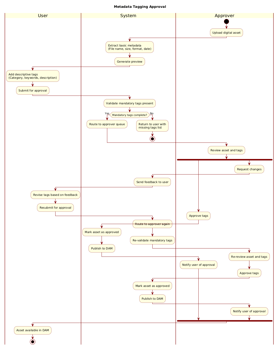
Diagram Abstraction & Representation: An activity diagram is the standard notation for modeling the flow of control within a system. Unlike a class diagram which focuses on static structure, this notation captures the dynamic behavior of a process. In this specific model, we are mapping a business process rather than a technical sequence. We utilize swimlanes to visually segregate responsibilities. This abstraction is critical because it immediately answers the question: “Who or what is responsible for this specific step?” Whether it is the automated extraction of file properties or the final human decision to publish, the swimlane makes the handoff points explicit.
Target Domain Scope & Scenario: The scope of this diagram is strictly limited to the ingestion and validation phase of the DAM lifecycle. We are not modeling the actual storage architecture or the network infrastructure. Instead, we focus on the data entry workflow: uploading an asset, enriching it with metadata, and passing it through a quality gate. The diagram intentionally excludes error handling for network failures, focusing instead on logical data validation (e.g., missing mandatory tags).
Key Takeaways & Educational Insights: By following this guide, you will learn how to implement swimlanes to clarify accountability, use conditional logic to enforce business rules (mandatory fields), and manage parallel flows (forks) to represent simultaneous outcomes like approval versus revision. This model ensures that your development team understands exactly when the system should stop the process and when it should loop back for user intervention.
Complete Diagram & Full Source Code
Before diving into the construction details, here is the final rendered output you will achieve. This diagram demonstrates a clean, professional look using the Rose theme, with clear separation of duties across the User, System, and Approver lanes.
@startuml
!include https://static.visual-paradigm.com/web/resources/plantuml-stdlib/themes/rose.puml

title Metadata Tagging Approval

|User|
|System|
|Approver|

start

:Upload digital asset;

|System|
:Extract basic metadata
(File name, size, format, date);

:Generate preview;

|User|
:Add descriptive tags
(Category, keywords, description);

:Submit for approval;

|System|
:Validate mandatory tags present;

if (Mandatory tags complete?) then (Yes)
  :Route to approver queue;
else (No)
  :Return to user with
  missing tags list;
  stop
endif

|Approver|
:Review asset and tags;

fork
  :Approve tags;
  |System|
  :Mark asset as approved;
  :Publish to DAM;
  |Approver|
  :Notify user of approval;
fork again
  :Request changes;
  |System|
  :Send feedback to user;
  |User|
  :Revise tags based on feedback;
  :Resubmit for approval;
  |System|
  :Route to approver again;
  :Re-validate mandatory tags;
  |Approver|
  :Re-review asset and tags;
  :Approve tags;
  |System|
  :Mark asset as approved;
  :Publish to DAM;
  |Approver|
  :Notify user of approval;
end fork

|User|
:Asset available in DAM;

stop
@endumlStep-by-Step Architectural Walkthrough
Constructing this diagram in VPasCode is a matter of logical sequencing. We will break down the code into four distinct phases to ensure you understand the architectural intent behind each syntax element.
Phase 1: Canvas Configuration & Layout Directives
Every PlantUML diagram begins with configuration directives that set the global theme and title. This ensures consistency across your documentation. In the code above, we start with @startuml to initialize the engine. Crucially, we include the Rose theme to give the diagram a polished, modern aesthetic without manual styling.
!include https://static.visual-paradigm.com/web/resources/plantuml-stdlib/themes/rose.puml

title Metadata Tagging Approval
The title directive is essential for accessibility and clarity, especially when embedding the diagram in larger documentation pages. It acts as the header for the visual representation.
Phase 2: Declaring Core Entities, Actors, and Boundaries
The foundation of a successful activity diagram is defining the swimlanes. Swimlanes allow us to partition the diagram horizontally, assigning specific actions to specific roles. In this workflow, we have three distinct actors: the User initiating the process, the System handling automation, and the Approver providing human oversight.
|User|
|System|
|Approver|
Once defined, these labels act as containers. Any action placed immediately after a label belongs to that specific entity until another label is encountered. This structure prevents the “spaghetti code” look common in complex diagrams where responsibilities are unclear.
Phase 3: Mapping Data Flows & Key Interactions
With the lanes defined, we map the chronological flow. The process begins at start and moves through the User uploading an asset. The System then takes over to extract metadata. Notice how the syntax |System| shifts the active lane back to the center column.
:Upload digital asset;

|System|
:Extract basic metadata
(File name, size, format, date);
We use the colon : prefix to denote an activity node. The text following it describes the action. We can use newlines within the text block (as seen in the metadata extraction step) to make the description more readable without breaking the flow logic.
Phase 4: Grouping, Annotations & Visual Polish
The most complex part of this workflow is the decision logic and the parallel processing. We use the if statement to validate data integrity. If mandatory tags are missing, the flow stops immediately.
if (Mandatory tags complete?) then (Yes)
  :Route to approver queue;
else (No)
  :Return to user with missing tags list;
  stop
endif
Following validation, we introduce a fork block. This represents a decision point where the process splits into two potential paths: Approval or Revision. The fork and fork again syntax allows us to define these parallel branches clearly, ensuring the diagram remains readable even when the logic branches out. The end fork statement merges the paths back together before the final stop node.
Syntax & Keyword Deep Dive
To master diagram-as-code, you must understand the specific keywords that drive the rendering engine. Here are the critical PlantUML syntax features used in this tutorial:
@startuml/@enduml: These are the mandatory delimiters. They tell the VPasCode editor where the diagram code begins and ends. Without them, the code will not render.|Lane Name|: This syntax defines a swimlane. It must be placed on its own line. It resets the context for all subsequent actions until a new lane is declared.:Action;: The colon indicates an activity node. The text following it is the label for the box. The semicolon is required to terminate the statement.if (Condition) then (Yes) ... endif: This creates a diamond-shaped decision node. The text inside the parentheses represents the condition being checked.fork/fork again/end fork: These keywords create parallel branches.forkstarts the split,fork againadds additional parallel branches, andend forkmerges them back into a single flow.start/stop: These define the entry and exit points of the activity flow, rendered as solid black circles.
Best Practices & Pitfalls to Avoid
When building activity diagrams for complex systems, adherence to best practices ensures your documentation remains maintainable over time.
Keep Swimlanes Balanced: Avoid creating a single lane that contains 80% of the actions. If the System lane is too crowded, consider splitting the logic into multiple subsystems or using sub-activity diagrams. In our example, the System lane handles extraction and validation, while the User handles input and revision, creating a balanced workload.
Minimize Cross-Lane Crossing: While PlantUML handles automatic routing, try to order your swimlanes logically (e.g., Frontend -> Backend -> Admin) so that flow lines travel primarily downwards rather than zigzagging across the page.
Use Descriptive Labels: Avoid vague labels like “Process Data.” Instead, use specific verbs like “Validate Mandatory Tags.” This makes the diagram useful for developers reading the code later.
Start Building Activity Diagrams Faster with VPasCode
Test your workflow logic instantly in your browser with zero setup, using VPasCode’s free PlantUML editor.