


In the rapidly evolving landscape of digital health, the ability to aggregate data from diverse wearable devices into a coherent, actionable system is paramount. Healthcare providers and patients alike rely on seamless data integration from smartwatches, medical sensors, and fitness trackers to monitor vital signs, track activity, and predict health risks. However, managing this influx of heterogeneous data requires a robust software architecture that can handle inheritance, data normalization, and secure storage without compromising performance.
Visualizing this architecture before writing a single line of production code is critical for system architects. A well-structured class diagram serves as a blueprint, clarifying how entities like User, WearableDevice, and DataAggregator interact. By leveraging diagram-as-code methodologies with PlantUML within the VPasCode editor, teams can maintain living documentation that evolves alongside the software, ensuring clarity and reducing architectural debt.

Understanding the Model: Purpose, Scope & Problem Framing
This tutorial focuses on constructing a Class Diagram for a Wearable Health Data Aggregation System. In the context of object-oriented design, a class diagram represents the static structure of a system by displaying its classes, attributes, methods, and the relationships among objects. This specific model is chosen because it effectively captures the domain entities of a healthcare IoT solution, distinguishing between the physical devices, the data they produce, and the logical services that process that data.
Diagram Abstraction & Representation: The model utilizes inheritance to represent device types (SmartWatch, FitnessTracker, MedicalSensor) under a common WearableDevice abstract class. This demonstrates how different hardware can be treated uniformly in the software layer. It also employs aggregation and composition to show ownership and lifecycle dependencies, such as how a DataAggregator holds HealthData objects.
Target Domain Scope & Scenario: The scope covers the ingestion pipeline from the device level up to the analytics and alerting layers. It intentionally excludes external network protocols or database implementation details to focus on the core business logic and object relationships. The boundaries include the User, the Device, the Data, and the Processing Engine.
Key Takeaways & Educational Insights: By completing this guide, you will gain insight into how to model abstract base classes in PlantUML, how to define cardinality in relationships (e.g., one User owns many Devices), and how to organize complex healthcare systems into manageable, logical components using the VPasCode web editor.
Complete Diagram & Full Source Code
Before diving into the step-by-step construction, examine the finished blueprint below. This visual representation encapsulates the full architecture, showing the flow from device generation to provider alerts.
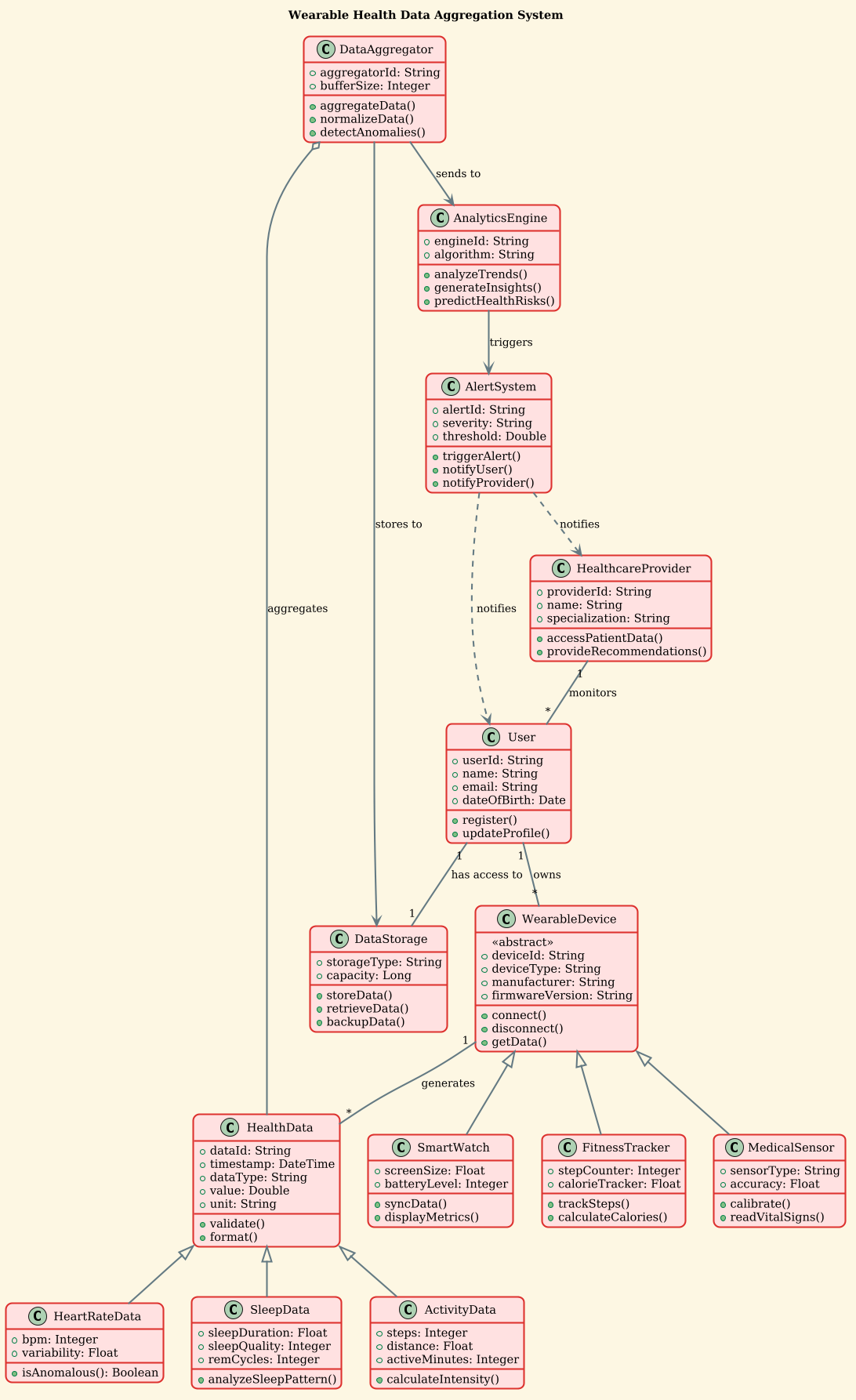
Copy the complete source code below to explore the diagram in the VPasCode interactive editor. This single block contains all directives, class definitions, and relationship mappings required to render the full system.
@startuml
!theme sunlust

title Wearable Health Data Aggregation System

/'
This system aggregates health data from various wearable devices such as smartwatches, fitness trackers, and medical sensors. It processes, stores, and analyzes the collected data to provide insights about user health metrics including heart rate, sleep patterns, activity levels, and vital signs. The system supports multiple device types, handles data normalization, and provides analytics services to healthcare providers and end users.
'/

class User {
    +userId: String
    +name: String
    +email: String
    +dateOfBirth: Date
    +register()
    +updateProfile()
}

class WearableDevice {
    <<abstract>>
    +deviceId: String
    +deviceType: String
    +manufacturer: String
    +firmwareVersion: String
    +connect()
    +disconnect()
    +getData()
}

class SmartWatch {
    +screenSize: Float
    +batteryLevel: Integer
    +syncData()
    +displayMetrics()
}

class FitnessTracker {
    +stepCounter: Integer
    +calorieTracker: Float
    +trackSteps()
    +calculateCalories()
}

class MedicalSensor {
    +sensorType: String
    +accuracy: Float
    +calibrate()
    +readVitalSigns()
}

class HealthData {
    +dataId: String
    +timestamp: DateTime
    +dataType: String
    +value: Double
    +unit: String
    +validate()
    +format()
}

class HeartRateData {
    +bpm: Integer
    +variability: Float
    +isAnomalous(): Boolean
}

class SleepData {
    +sleepDuration: Float
    +sleepQuality: Integer
    +remCycles: Integer
    +analyzeSleepPattern()
}

class ActivityData {
    +steps: Integer
    +distance: Float
    +activeMinutes: Integer
    +calculateIntensity()
}

class DataAggregator {
    +aggregatorId: String
    +bufferSize: Integer
    +aggregateData()
    +normalizeData()
    +detectAnomalies()
}

class DataStorage {
    +storageType: String
    +capacity: Long
    +storeData()
    +retrieveData()
    +backupData()
}

class AnalyticsEngine {
    +engineId: String
    +algorithm: String
    +analyzeTrends()
    +generateInsights()
    +predictHealthRisks()
}

class HealthcareProvider {
    +providerId: String
    +name: String
    +specialization: String
    +accessPatientData()
    +provideRecommendations()
}

class AlertSystem {
    +alertId: String
    +severity: String
    +threshold: Double
    +triggerAlert()
    +notifyUser()
    +notifyProvider()
}

User "1" -- "*" WearableDevice : owns
WearableDevice <|-- SmartWatch
WearableDevice <|-- FitnessTracker
WearableDevice <|-- MedicalSensor
WearableDevice "1" -- "*" HealthData : generates
HealthData <|-- HeartRateData
HealthData <|-- SleepData
HealthData <|-- ActivityData
DataAggregator o-- HealthData : aggregates
DataAggregator --> DataStorage : stores to
DataAggregator --> AnalyticsEngine : sends to
AnalyticsEngine --> AlertSystem : triggers
User "1" -- "1" DataStorage : has access to
HealthcareProvider "1" -- "*" User : monitors
AlertSystem ..> HealthcareProvider : notifies
AlertSystem ..> User : notifies

@endumlStep-by-Step Architectural Walkthrough
Constructing this diagram requires a logical progression from global settings to specific entity definitions. Follow these phases to replicate the model in VPasCode.
Phase 1: Canvas Configuration & Layout Directives
Every PlantUML diagram begins with configuration directives that set the visual style and metadata. In this healthcare scenario, we want a clean, professional look that emphasizes readability.
First, we initialize the diagram block and apply a specific visual theme. The !theme sunlust directive applies a warm, modern color palette suitable for medical applications.
!theme sunlustNext, we define the diagram title and add a comment block to document the system’s purpose. This documentation is embedded directly in the code, ensuring the diagram description travels with the file.
title Wearable Health Data Aggregation System

/'
This system aggregates health data from various wearable devices...
'/
Phase 2: Declaring Core Entities, Actors, and Boundaries
The foundation of the model lies in the core entities. We start with the User and the WearableDevice hierarchy. Using the class keyword, we define the attributes and methods for each.
For WearableDevice, we use the <<abstract>> stereotype. This indicates that no specific instance of WearableDevice exists directly; instead, it serves as a parent for specific types like SmartWatch and FitnessTracker.
class WearableDevice {
    <>
    +deviceId: String
    +connect()
    +disconnect()
}
Similarly, we define SmartWatch and MedicalSensor with their specific attributes like screenSize and accuracy, ensuring the model reflects real-world hardware capabilities.
Phase 3: Mapping Data Flows & Key Interactions
Once entities are defined, we establish the relationships that drive the system. This phase focuses on how data moves from devices to storage.
We use the -- syntax to define associations. For example, a User owns multiple devices, denoted by the cardinality "1" -- "*".
User "1" -- "*" WearableDevice : ownsFor data inheritance, we use the <|-- arrow to show that HeartRateData is a specialized form of HealthData. This allows the system to treat all health metrics uniformly while preserving specific details.
HealthData <|-- HeartRateDataThe processing logic is modeled via aggregation and association. The DataAggregator aggregates HealthData using an aggregation relationship (o--), implying the data can exist independently of the aggregator.
DataAggregator o-- HealthData : aggregatesPhase 4: Grouping, Annotations & Visual Polish
The final phase connects the system to external stakeholders and safety mechanisms. We introduce HealthcareProvider and AlertSystem to complete the ecosystem.
We use dependency arrows (..>) to show notification flows. The AlertSystem does not own the provider, but it notifies them when thresholds are breached.
AlertSystem ..> HealthcareProvider : notifiesThis structure ensures the diagram remains readable while capturing the critical safety loops required in healthcare software.
Syntax & Keyword Deep Dive
Understanding the specific PlantUML syntax used in this diagram is essential for extending the model in the future. Here is a breakdown of the key keywords and conventions:
class: Defines a class or component. Used for all entities likeUserandDataStorage.<<abstract>>: Stereotype marking a class as abstract, meaning it cannot be instantiated directly. Used onWearableDevice.<|--: Represents Generalization (Inheritance). The arrow points to the parent class (e.g.,SmartWatchinherits fromWearableDevice).--: Represents Association. A simple link between two classes (e.g.,UsertoWearableDevice).o--: Represents Aggregation. A "whole-part" relationship where the part can exist without the whole (e.g.,DataAggregatorandHealthData).-->: Represents Dependency or Flow. Indicates that one class uses another (e.g.,AnalyticsEnginetriggersAlertSystem)...>: Represents a dashed Dependency. Often used for notification or signal flows rather than direct object references.title: Sets the header text displayed above the diagram./' ... '/: Creates a multi-line comment block for documentation.
Best Practices & Pitfalls to Avoid
When modeling complex healthcare systems with PlantUML, adhere to these guidelines to maintain diagram quality:
- Maintain Abstraction Levels: Do not mix high-level architectural components with low-level implementation details (like database SQL queries) in the same class diagram. Keep the focus on object relationships.
- Use Cardinality Explicitly: Always specify relationship multiplicities (e.g.,
"1","*") to avoid ambiguity about data ownership and user limits. - Consistent Naming Conventions: Use PascalCase for class names and camelCase for methods to ensure the diagram is readable for developers.
- Modularize Complex Logic: If the diagram becomes too crowded, consider splitting it into subsystem diagrams (e.g., one for Devices, one for Analytics) and linking them via references.
Start Building Wearable Health System Diagrams Faster with VPasCode
Instantly render, edit, and customize this PlantUML class diagram online in VPasCode without installing any local tools or dependencies.