


In the high-velocity environment of modern logistics, the margin for error during inventory receiving is virtually non-existent. A Warehouse Management System (WMS) serves as the digital nervous system of a distribution center, coordinating physical movement with data integrity. When an inbound shipment arrives, the discrepancy between expected goods (ASN) and physical reality must be resolved instantly to prevent bottlenecks, stock discrepancies, and downstream fulfillment failures. Visualizing this complex interaction through a sequence diagram provides the architectural clarity needed to align engineering teams with operational realities.

Diagramming-as-code has revolutionized how architects document these temporal flows. Unlike static drawing tools, writing code allows for versioning logic, automated testing of diagram syntax, and rapid iteration of complex scenarios like quality checks or put-away exceptions. By using PlantUML within the VPasCode web editor, logistics engineers can prototype these workflows instantly without installing local dependencies. This tutorial walks you through building a professional sequence diagram that captures the full lifecycle of receiving, validation, quality control, and put-away, ensuring your documentation is as robust as your warehouse operations.
Understanding the Model: Purpose, Scope & Problem Framing
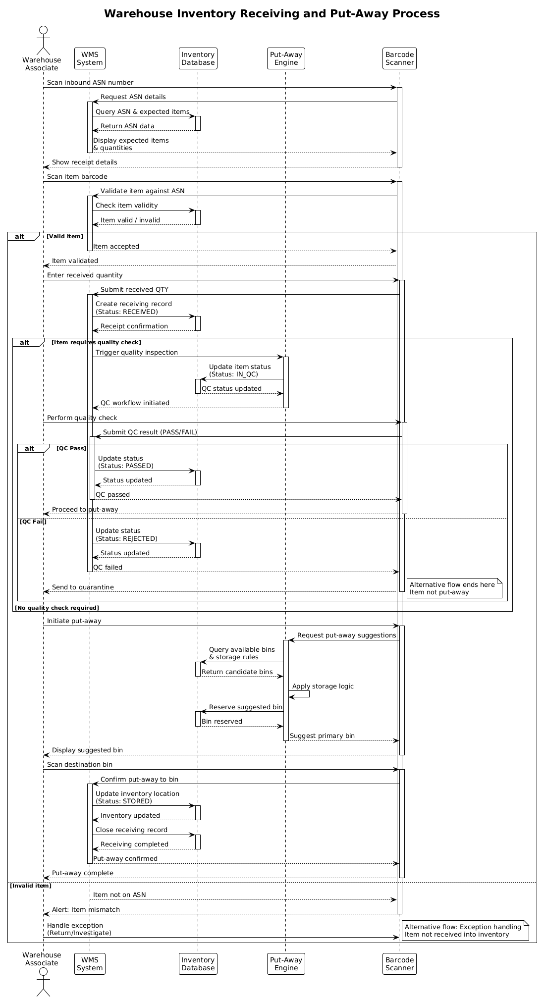
This diagram models a Sequence Diagram, which is the definitive tool for illustrating runtime interactions between system components over time. In the context of logistics, a sequence diagram answers critical questions: Who initiates the action? How does the WMS validate data against the database? What happens when an item fails quality inspection?
Diagram Abstraction & Representation
We use lifelines (vertical dashed lines) to represent persistent entities like the Warehouse Associate or the WMS System. Horizontal arrows represent messages (data requests or commands) passed between these entities. The activation bars (rectangles on lifelines) indicate when a participant is actively processing a request. This abstraction allows us to focus on the flow of control and data without getting bogged down in implementation details like API endpoints or database schema.
Target Domain Scope & Scenario
The scope is strictly limited to the Inbound Receiving module of a WMS. It begins when an ASN (Advanced Shipping Notice) is scanned and ends when the inventory status is updated to STORED. It explicitly includes alternative flows for Quality Checks (QC) and Item Mismatches, which are common failure points in warehouse operations.
Key Takeaways & Educational Insights
By constructing this model, you will learn how to manage complex conditional logic using alt and else blocks. You will also understand how to model asynchronous feedback loops, such as a barcode scanner waiting for database confirmation before displaying results to the user. This clarity is essential for reducing ambiguity in technical specifications.
Complete Diagram & Full Source Code
Below is the finished blueprint for the Warehouse Inventory Receiving process. You can visualize the interactions between the Associate, Scanner, WMS, and Database before diving into the construction steps.
@startuml

!theme plain

title Warehouse Inventory Receiving and Put-Away Process

/'
This sequence diagram illustrates the inventory receiving and put-away flow
in a Warehouse Management System (WMS). It covers the end-to-end process
from ASN receipt to bin assignment, including alternative flows for
quality checks and put-away exceptions.
'/

actor "Warehouse\nAssociate" as Associate
participant "WMS\nSystem" as WMS
participant "Inventory\nDatabase" as DB
participant "Put-Away\nEngine" as PutEngine
participant "Barcode\nScanner" as Scanner

Associate -> Scanner : Scan inbound ASN number
activate Scanner
Scanner -> WMS : Request ASN details
activate WMS
WMS -> DB : Query ASN & expected items
activate DB
DB --> WMS : Return ASN data
deactivate DB
WMS --> Scanner : Display expected items\n& quantities
deactivate WMS
Scanner --> Associate : Show receipt details
deactivate Scanner

Associate -> Scanner : Scan item barcode
activate Scanner
Scanner -> WMS : Validate item against ASN
activate WMS
WMS -> DB : Check item validity
activate DB
DB --> WMS : Item valid / invalid
deactivate DB

alt Valid item
    WMS --> Scanner : Item accepted
    deactivate WMS
    Scanner --> Associate : Item validated

    Associate -> Scanner : Enter received quantity
    activate Scanner
    Scanner -> WMS : Submit received QTY
    activate WMS
    WMS -> DB : Create receiving record\n(Status: RECEIVED)
    activate DB
    DB --> WMS : Receipt confirmation
    deactivate DB

    alt Item requires quality check
        WMS -> PutEngine : Trigger quality inspection
        activate PutEngine
        PutEngine -> DB : Update item status\n(Status: IN_QC)
        activate DB
        DB --> PutEngine : QC status updated
        deactivate DB
        PutEngine --> WMS : QC workflow initiated
        deactivate PutEngine

        Associate -> Scanner : Perform quality check
        activate Scanner
        Scanner -> WMS : Submit QC result (PASS/FAIL)
        activate WMS

        alt QC Pass
            WMS -> DB : Update status\n(Status: PASSED)
            activate DB
            DB --> WMS : Status updated
            deactivate DB
            WMS --> Scanner : QC passed
            deactivate WMS
            Scanner --> Associate : Proceed to put-away
            deactivate Scanner
        else QC Fail
            WMS -> DB : Update status\n(Status: REJECTED)
            activate DB
            DB --> WMS : Status updated
            deactivate DB
            WMS --> Scanner : QC failed
            deactivate WMS
            Scanner --> Associate : Send to quarantine
            deactivate Scanner
            note right : Alternative flow ends here\nItem not put-away
        end
    else No quality check required
        note right : Skip QC, proceed\ndirectly to put-away
    end

    Associate -> Scanner : Initiate put-away
    activate Scanner
    Scanner -> PutEngine : Request put-away suggestions
    activate PutEngine
    PutEngine -> DB : Query available bins\n& storage rules
    activate DB
    DB --> PutEngine : Return candidate bins
    deactivate DB
    PutEngine -> PutEngine : Apply storage logic
    PutEngine -> DB : Reserve suggested bin
    activate DB
    DB --> PutEngine : Bin reserved
    deactivate DB
    PutEngine --> Scanner : Suggest primary bin
    deactivate PutEngine
    Scanner --> Associate : Display suggested bin
    deactivate Scanner

    Associate -> Scanner : Scan destination bin
    activate Scanner
    Scanner -> WMS : Confirm put-away to bin
    activate WMS
    WMS -> DB : Update inventory location\n(Status: STORED)
    activate DB
    DB --> WMS : Inventory updated
    deactivate DB
    WMS -> DB : Close receiving record
    activate DB
    DB --> WMS : Receiving completed
    deactivate DB
    WMS --> Scanner : Put-away confirmed
    deactivate WMS
    Scanner --> Associate : Put-away complete
    deactivate Scanner

else Invalid item
    WMS --> Scanner : Item not on ASN
    deactivate WMS
    Scanner --> Associate : Alert: Item mismatch
    deactivate Scanner
    Associate -> Scanner : Handle exception\n(Return/Investigate)
    note right : Alternative flow: Exception handling\nItem not received into inventory
end
@endumlStep-by-Step Architectural Walkthrough
Building this diagram requires a logical progression from configuration to interaction mapping. Follow these phases to construct the model in VPasCode.
Phase 1: Canvas Configuration & Layout Directives
Every PlantUML diagram starts with setup. We define the visual theme and the diagram title to ensure consistency across your documentation. The !theme plain directive removes default styling, giving you a clean slate to focus on logic.
@startuml

!theme plain

title Warehouse Inventory Receiving and Put-Away Process

/'
This sequence diagram illustrates the inventory receiving and put-away flow
in a Warehouse Management System (WMS). It covers the end-to-end process
from ASN receipt to bin assignment, including alternative flows for
quality checks and put-away exceptions.
'/
The comment block /' ... '/ is crucial for documentation. It allows you to describe the diagram’s intent without affecting the rendered output, a best practice for living documentation.
Phase 2: Declaring Core Entities, Actors, and Boundaries
Before drawing arrows, we must define the participants. In sequence diagrams, these are the “lifelines”. We use actor for human users and participant for software systems.
actor "Warehouse\nAssociate" as Associate
participant "WMS\nSystem" as WMS
participant "Inventory\nDatabase" as DB
participant "Put-Away\nEngine" as PutEngine
participant "Barcode\nScanner" as Scanner
Note the use of \n in the labels (e.g., “Warehouse\nAssociate”). This forces a line break, preventing the lifeline from becoming too wide and cluttering the diagram. Assigning an alias (e.g., as Associate) allows us to reference them concisely later.
Phase 3: Mapping Data Flows & Key Interactions
This is the core of the diagram. We map the synchronous messages using --> and asynchronous returns using --> with a dashed line. We wrap these interactions with activate and deactivate to show processing time.
Associate -> Scanner : Scan inbound ASN number
activate Scanner
Scanner -> WMS : Request ASN details
activate WMS
WMS -> DB : Query ASN & expected items
activate DB
DB --> WMS : Return ASN data
deactivate DB
We then introduce conditional logic using the alt block. This represents the decision point where the system checks if the item is valid. The alt block allows us to model multiple branches (e.g., Valid vs. Invalid) within a single diagram.
alt Valid item
    [Valid flow logic]
else Invalid item
    [Exception flow logic]
end
Phase 4: Grouping, Annotations & Visual Polish
To make the diagram readable, we add notes to explain complex branches, such as when an item is rejected. Notes are added using the note right or note left syntax.
note right : Alternative flow ends here\nItem not put-away
This annotation appears next to the lifeline, providing context without cluttering the message flow. This phase ensures the diagram is not just functional code, but a clear visual artifact for stakeholders.
Syntax & Keyword Deep Dive
Understanding the specific PlantUML keywords is essential for mastering sequence diagrams. Here are the critical elements used in this tutorial:
@startuml: The mandatory opening tag that tells the renderer this is a PlantUML diagram.actor/participant: Defines the vertical lifelines.actortypically represents a human user, whileparticipantrepresents a system component.-->(Solid Arrow): Represents a synchronous message or request (e.g., “Scan item”).-->(Dashed Arrow): Represents an asynchronous return message (e.g., “Return ASN data”).activate/deactivate: Controls the width of the activation bar on the lifeline, indicating when an object is busy processing.alt/else/end: Creates a combined fragment block to represent conditional logic (If/Else) or loops.note right: Adds an annotation box to the right of a specific lifeline or message.!theme plain: A directive to override default styling with a clean, minimal theme.
Best Practices & Pitfalls to Avoid
To maintain high-quality diagrams in VPasCode, adhere to these modeling standards:
- Keep Lifelines Concise: Avoid overly long labels. Use aliases (e.g.,
as WMS) to keep the diagram width manageable. - Balance Activation Bars: Don’t overuse
activate. Only activate a lifeline when it is actively processing. Too many activations create visual noise. - Group Complex Logic: Use
altblocks to group alternative flows. This keeps the main happy path clear while isolating exception handling. - Use Comments for Context: Never rely solely on the diagram. Use the
/' ... '/comment block to explain the “Why” behind the flow, not just the “What”.
Try It Yourself with VPasCode
Start Building PlantUML Diagrams Faster with VPasCode
Immediately test, preview, and customize this Warehouse Receiving sequence diagram online in VPasCode without installing any tools.