


In modern manufacturing environments, maintaining rigorous quality standards requires precise coordination between enterprise systems and automated hardware. When a production batch reaches the inspection station, the interaction between the Manufacturing Execution System (MES), scheduling logic, camera controllers, and image processing pipelines must be flawlessly synchronized. A single miscommunication can lead to defective products passing through or valid batches being rejected, impacting both cost and customer trust.

Visualizing these interactions is critical before implementation. Sequence diagrams provide a chronological view of object interactions, making them ideal for mapping the temporal flow of data from image capture to defect classification. By using diagram-as-code with PlantUML in VPasCode, architects can define these complex workflows textually, ensuring version-free clarity and immediate visual feedback without the overhead of manual drawing tools.
Understanding the Model: Purpose, Scope & Problem Framing
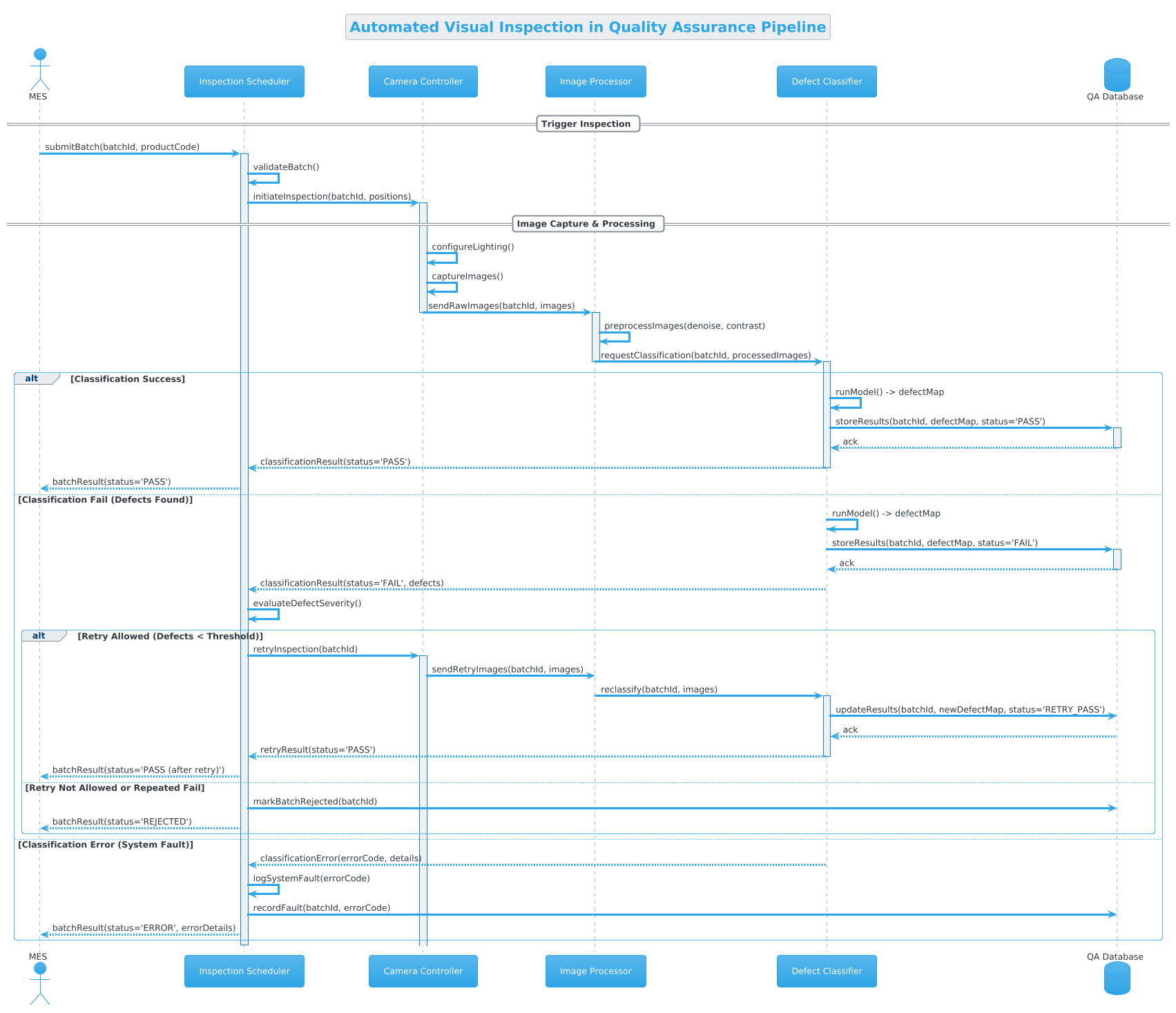
This diagram focuses on the Automated Visual Inspection workflow within a Quality Assurance Pipeline System. In this manufacturing context, the primary challenge is managing the lifecycle of a product batch as it moves through verification stages.
Diagram Abstraction & Representation
A sequence diagram is the appropriate choice here because it captures when actions occur, not just what happens. It models the runtime messaging between distinct system components. The lifelines represent active participants like the MES (orchestrator), Scheduler (logic engine), Camera Controller (hardware interface), and Defect Classifier (AI/Logic endpoint). The horizontal arrows represent method calls or data packets, while vertical activation bars indicate the duration of processing.
Target Domain Scope & Scenario
The scope is strictly limited to the inspection phase. It does not cover upstream production or downstream logistics. The diagram explicitly models the boundary between the MES initiating a batch and the system returning a final status (PASS, FAIL, or REJECTED). It also encapsulates internal logic flows, such as image preprocessing and classification retries, which are often hidden in high-level architectural views.
Key Takeaways & Educational Insights
By constructing this model, you will gain clarity on how to handle asynchronous hardware responses, manage error states within a pipeline, and structure conditional logic (such as retry mechanisms) using standard PlantUML combined fragments. This ensures your documentation remains a living artifact that accurately reflects the system’s operational reality.
Complete Diagram & Full Source Code
Below is the finalized blueprint for the Automated Visual Inspection workflow. You can view the rendered output immediately by pasting the code into the VPasCode editor.
@startuml
!theme cerulean

title Automated Visual Inspection in Quality Assurance Pipeline

/'
This sequence diagram illustrates the Automated Visual Inspection workflow
within a Quality Assurance Pipeline System. It covers the interaction between
the MES, Inspection Scheduler, Camera Controller, Image Processor, and the
Defect Classifier. Alternative flows are included for pass, fail, and
retry scenarios.
'/

actor "MES" as MES
participant "Inspection Scheduler" as Scheduler
participant "Camera Controller" as Camera
participant "Image Processor" as Processor
participant "Defect Classifier" as Classifier
database "QA Database" as DB

== Trigger Inspection ==
MES -> Scheduler: submitBatch(batchId, productCode)
activate Scheduler
Scheduler -> Scheduler: validateBatch()
Scheduler -> Camera: initiateInspection(batchId, positions)

== Image Capture & Processing ==
activate Camera
Camera -> Camera: configureLighting()
Camera -> Camera: captureImages()
Camera -> Processor: sendRawImages(batchId, images)
deactivate Camera

activate Processor
Processor -> Processor: preprocessImages(denoise, contrast)
Processor -> Classifier: requestClassification(batchId, processedImages)
deactivate Processor

activate Classifier

alt Classification Success
    Classifier -> Classifier: runModel() -> defectMap
    Classifier -> DB: storeResults(batchId, defectMap, status='PASS')
    activate DB
    DB --> Classifier: ack
    deactivate DB
    Classifier --> Scheduler: classificationResult(status='PASS')
    deactivate Classifier
    Scheduler --> MES: batchResult(status='PASS')

else Classification Fail (Defects Found)
    Classifier -> Classifier: runModel() -> defectMap
    Classifier -> DB: storeResults(batchId, defectMap, status='FAIL')
    activate DB
    DB --> Classifier: ack
    deactivate DB
    Classifier --> Scheduler: classificationResult(status='FAIL', defects)
    deactivate Classifier
    Scheduler -> Scheduler: evaluateDefectSeverity()

    alt Retry Allowed (Defects < Threshold)
        Scheduler -> Camera: retryInspection(batchId)
        activate Camera
        Camera -> Processor: sendRetryImages(batchId, images)
        Processor -> Classifier: reclassify(batchId, images)
        activate Classifier
        Classifier -> DB: updateResults(batchId, newDefectMap, status='RETRY_PASS')
        DB --> Classifier: ack
        Classifier --> Scheduler: retryResult(status='PASS')
        deactivate Classifier
        Scheduler --> MES: batchResult(status='PASS (after retry)')
    else Retry Not Allowed or Repeated Fail
        Scheduler -> DB: markBatchRejected(batchId)
        Scheduler --> MES: batchResult(status='REJECTED')
    end

else Classification Error (System Fault)
    Classifier --> Scheduler: classificationError(errorCode, details)
    deactivate Classifier
    Scheduler -> Scheduler: logSystemFault(errorCode)
    Scheduler -> DB: recordFault(batchId, errorCode)
    Scheduler --> MES: batchResult(status='ERROR', errorDetails)
end

deactivate Scheduler


@endumlStep-by-Step Architectural Walkthrough
Constructing this diagram in VPasCode involves four distinct phases: setting the visual theme, defining participants, mapping the primary flow, and handling complex conditional logic.
Phase 1: Canvas Configuration & Layout Directives
Every PlantUML diagram begins with setup directives. We start with @startuml to initialize the engine. We then apply !theme cerulean to give the diagram a consistent, professional color palette suitable for technical documentation. The title directive provides a clear header, while the comment block /' ... '/ offers a human-readable description that is rendered in the diagram metadata but does not clutter the visual flow.
@startuml
!theme cerulean
title Automated Visual Inspection in Quality Assurance Pipeline
/'
This sequence diagram illustrates...
'/
Phase 2: Declaring Core Entities, Actors, and Boundaries
Next, we define the participants. In manufacturing systems, roles are distinct. We use actor for the external system initiating the process (MES), participant for internal software services (Scheduler, Processor), and database for persistent storage (QA Database). Naming them with aliases (e.g., as Scheduler) allows us to reference them concisely in the interaction flows.
actor "MES" as MES
participant "Inspection Scheduler" as Scheduler
participant "Camera Controller" as Camera
participant "Image Processor" as Processor
participant "Defect Classifier" as Classifier
database "QA Database" as DB
Phase 3: Mapping Data Flows & Key Interactions
We organize the timeline using == headers to create logical sections like Trigger Inspection and Image Capture & Processing. Messages flow left-to-right for synchronous calls (e.g., MES -> Scheduler) and right-to-left for return messages (e.g., DB --> Classifier). The activate and deactivate keywords are crucial here; they visually represent the processing time for each component, showing exactly when the Scheduler is busy validating a batch versus when it is idle.
MES -> Scheduler: submitBatch(batchId, productCode)
activate Scheduler
Scheduler -> Scheduler: validateBatch()
Scheduler -> Camera: initiateInspection(batchId, positions)
Phase 4: Grouping, Annotations & Visual Polish
Real-world systems are not linear. We use alt (alternative) and else blocks to model decision points. For instance, after classification, the system must decide if the batch passed, failed, or encountered an error. Nested alt blocks handle the retry logic: if defects are found but below a threshold, a retry is triggered; otherwise, the batch is rejected. This structure ensures the diagram accurately reflects the business rules of the Quality Assurance Pipeline.
alt Classification Success
    Classifier -> DB: storeResults(batchId, defectMap, status='PASS')
else Classification Fail (Defects Found)
    Classifier -> DB: storeResults(batchId, defectMap, status='FAIL')
end
Syntax & Keyword Deep Dive
Understanding the specific PlantUML syntax allows you to extend this diagram for more complex scenarios. Below are the key keywords utilized in this workflow.
actor: Represents an external entity initiating the process, such as the MES system.participant: Denotes a software component or service within the system boundary, like the Scheduler or Processor.database: Specifically styles the lifeline to indicate data persistence, used here for the QA Database.activate/deactivate: Controls the vertical activation bar on a lifeline, indicating when a component is actively processing a request.== Header ==: Creates a named section header to group related interactions chronologically.alt ... else ... end: Defines alternative paths. The diagram renders only one of the blocks based on logical conditions, such asClassification Successvs.Classification Fail.->/-->:->indicates a synchronous message call (request), while-->indicates a return message or response.
Best Practices & Pitfalls to Avoid
To maintain high-quality documentation in VPasCode, follow these modeling guidelines:
- Keep Lifelines Concise: Avoid overcrowding a single diagram. If a workflow spans multiple distinct phases (e.g., Setup vs. Execution), consider splitting them into separate diagrams rather than one massive sequence.
- Use Descriptive Message Labels: Always include parameters in message labels (e.g.,
submitBatch(batchId, productCode)) to clarify what data is being transferred. - Limit Nesting Depth: While PlantUML supports deep nesting, try to keep
altblocks to two levels maximum to preserve readability for stakeholders. - Consistent Naming: Use consistent aliases (e.g., always use
DBinstead of switching betweenDatabaseandDB) to prevent confusion in the message flows.
Try It Yourself with VPasCode
Start Building PlantUML Sequence Diagrams Faster with VPasCode
Experience instant live browser preview and zero local installation to prototype your manufacturing workflows online in VPasCode without installing any tools.