


In the rapidly evolving landscape of fintech and customer loyalty programs, clarity in transactional workflows is paramount. A Loyalty Points Redemption System is not merely a feature; it is a critical financial interface where accuracy, security, and user experience converge. Architects and developers often face the challenge of documenting complex conditional logic—such as balance validation, inventory locking, and parallel processing—without creating visual clutter.

This is where diagramming-as-code with PlantUML within VPasCode transforms the development lifecycle. By treating diagrams as text, teams can prototype financial processes instantly in the browser, ensuring that the visual representation of the system matches the logic implemented in the backend. This tutorial guides you through building a professional Activity Diagram that models the redemption lifecycle, utilizing swimlanes to delineate responsibilities between the Customer, the Front-end System, and the Backend Services.
Understanding the Model: Purpose, Scope & Problem Framing
Before diving into the syntax, it is essential to understand the architectural abstraction we are modeling. An Activity Diagram in PlantUML is the ideal tool for visualizing the dynamic behavior of a system, specifically focusing on the flow of control and data.
Diagram Abstraction & Representation
This specific model represents a business process flow. Unlike a Sequence Diagram which focuses on object interaction over time, an Activity Diagram focuses on the steps required to achieve a goal. We use swimlanes to partition the diagram into functional domains. This visual separation is critical in finance to ensure auditability: it clearly shows which actor initiates an action, which system validates it, and which backend service executes the state change.
Target Domain Scope & Scenario
The scope of this diagram is the Redemption Transaction. It intentionally excludes the user login process or the initial points earning phase to maintain focus on the specific problem of converting points into value. The boundaries are defined by the start node (customer selection) and the stop node (confirmation or rejection). This abstraction allows developers to isolate the logic for unit testing and integration testing without the noise of peripheral system states.
Key Takeaways & Educational Insights
By constructing this model, you will gain insight into how to handle parallel processing (forking) in financial transactions—ensuring inventory updates and ledger deductions happen simultaneously. You will also learn how to manage decision points (if/else) to handle edge cases like insufficient funds gracefully, a common requirement in banking and loyalty integrations.
Complete Diagram & Full Source Code
Below is the finished blueprint of the Loyalty Points Redemption process. This diagram utilizes the sunlust theme for a modern aesthetic and clearly defines the flow between the Customer, System, and Backend.
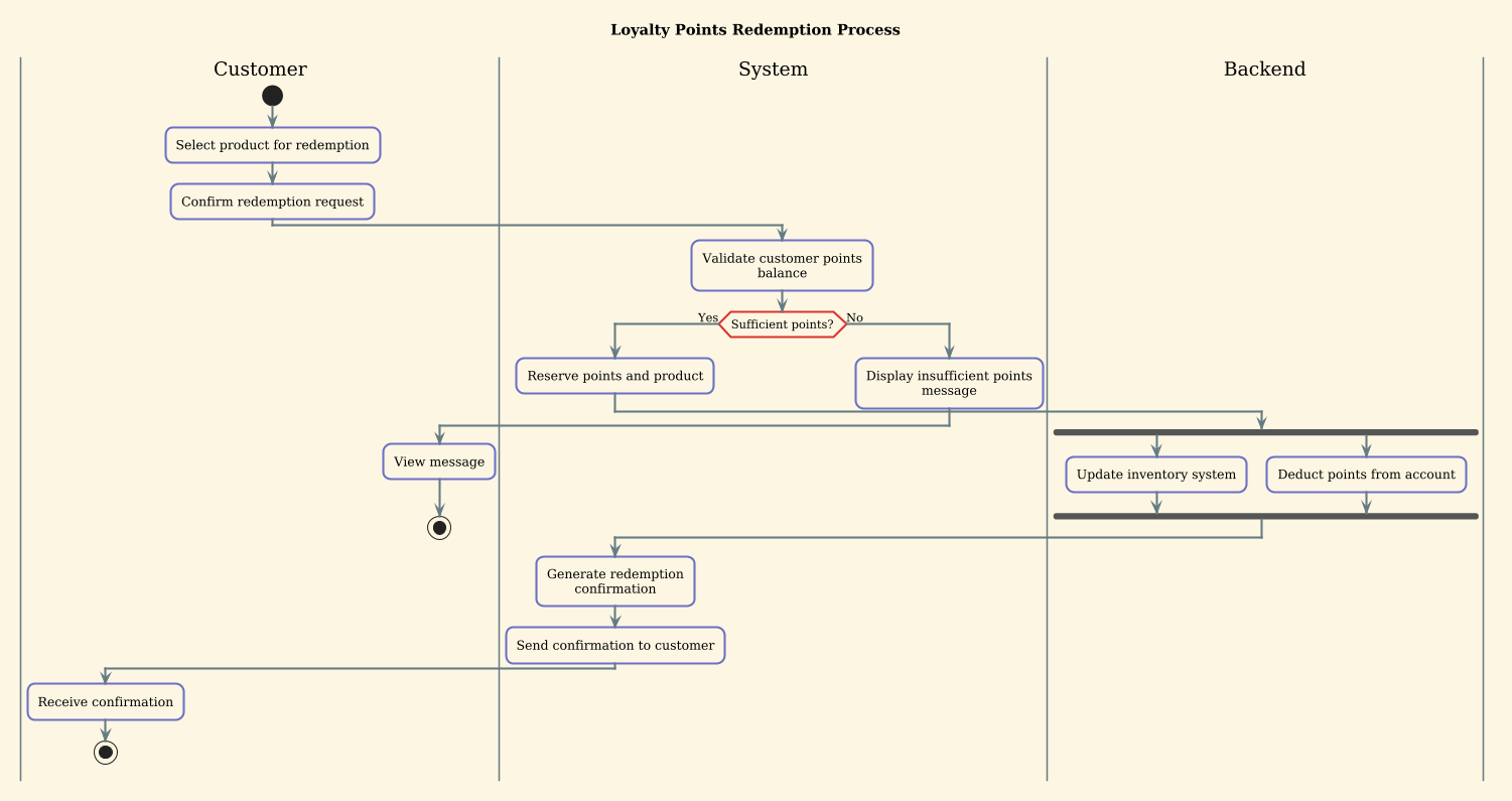
Copy the following complete source code to reproduce this diagram instantly in the VPasCode web editor.
@startuml
!theme sunlust
title Loyalty Points Redemption Process

|Customer|
|System|
|Backend|

|Customer|
start
:Select product for redemption;

|Customer|
:Confirm redemption request;

|System|
:Validate customer points balance;

if (Sufficient points?) then (Yes)
  :Reserve points and product;
  |Backend|
  fork
    :Update inventory system;
  fork again
    :Deduct points from account;
  end fork
  |System|
  :Generate redemption confirmation;
  :Send confirmation to customer;
  |Customer|
  :Receive confirmation;
  stop
else (No)
  |System|
  :Display insufficient points message;
  |Customer|
  :View message;
  stop
endif
@endumlStep-by-Step Architectural Walkthrough
Building this diagram in VPasCode is an iterative process. We will break down the construction into four logical phases to ensure you understand how each component contributes to the final architecture.
Phase 1: Canvas Configuration & Layout Directives
Every PlantUML diagram begins with initialization directives. These set the global rules for rendering. We start by declaring the diagram type using @startuml. Next, we apply the !theme sunlust directive. This ensures the diagram adopts a cohesive color palette and styling, making it suitable for professional documentation.
We also define the title directive to provide context immediately upon rendering. This metadata is crucial for documentation repositories and slide decks.
@startuml
!theme sunlust
title Loyalty Points Redemption Process
Phase 2: Declaring Core Entities, Actors, and Boundaries
The foundation of an Activity Diagram with swimlanes is the definition of the lanes themselves. Swimlanes represent the actors or system components responsible for specific actions. In this finance scenario, we have three distinct boundaries:
- Customer: The external user initiating the request.
- System: The application layer handling validation and communication.
- Backend: The core services managing data integrity and inventory.
We declare these using the pipe syntax |Name|. Note that VPasCode allows you to switch lanes mid-diagram, which is essential for showing hand-offs between components.
|Customer|
|System|
|Backend|
Phase 3: Mapping Data Flows & Key Interactions
This phase involves the core logic. We begin with the start node, representing the entry point. The flow moves from the Customer selecting a product to confirming the request. Crucially, we introduce a decision node using the if statement.
:Select product for redemption;
:Confirm redemption request;
:Validate customer points balance;

if (Sufficient points?) then (Yes)
  ...
else (No)
  ...
endif
Within the Yes branch, we encounter a fork statement. In financial systems, operations like updating inventory and deducting points must often occur atomically or in parallel to prevent race conditions. The fork and fork again directives allow us to visualize these concurrent threads of execution clearly.
Phase 4: Grouping, Annotations & Visual Polish
The final phase ensures the diagram terminates correctly. Every flow must end at a stop node. We ensure that both the success path (confirmation) and the failure path (insufficient points) lead to a stop node. This prevents “orphaned” flows in the diagram, which is a common best practice for maintainable documentation.
:Receive confirmation;
stop
...
:View message;
stop
Syntax & Keyword Deep Dive
To fully leverage VPasCode and PlantUML, understanding the specific keywords used in this finance diagram is essential. Below is a breakdown of the critical syntax elements:
title: Defines the header of the diagram. It appears at the top of the rendered output and is vital for identifying the specific process context.|Lane|: Declares a swimlane. Placing this before a node assigns that node to the specified actor. This is crucial for separating concerns in complex workflows.if (Condition) then (Branch): Represents a decision point. It splits the flow based on a boolean condition. In our case, it checks the points balance.fork/fork again/end fork: These keywords create parallel branches. Theforksplits the flow, andend forkmerges them back together. This is used here to show simultaneous inventory and ledger updates.start/stop: Define the entry and exit points of the activity. Every valid activity diagram must have exactly one start and one or more stops.!theme sunlust: A directive that applies a specific visual theme to the diagram, overriding default colors and shapes for a consistent look.
Best Practices & Pitfalls to Avoid
When modeling financial workflows with PlantUML in VPasCode, adhere to these architectural guidelines to maintain clarity:
- Maintain Swimlane Consistency: Ensure that actions logically belong to the lane you assign them to. For example, a backend database query should reside in the
Backendlane, not theSystemlane, to accurately reflect responsibility. - Balance Parallel Flows: When using
forkblocks, ensure all branches are balanced. If one branch takes significantly longer than another, consider adding wait states or explicit synchronization points to avoid confusion. - Handle Failure Paths Explicitly: In finance, success is only half the story. Always ensure your
elsebranches in decision nodes lead to a validstopnode or a retry mechanism. Never leave a failure path dangling. - Keep Diagrams Modular: If the redemption process becomes too complex (e.g., adding tax calculations, fraud checks), consider splitting the diagram into sub-activities or creating a separate diagram for the validation logic to keep the main flow readable.
Try It Yourself with VPasCode
Start Building PlantUML Activity Diagrams Faster with VPasCode
Test, preview, and customize this Loyalty Points workflow instantly in your browser without installing any tools or configuring local environments.