


In the rapidly evolving landscape of telecommunications, network architects face the constant challenge of managing complex routing infrastructures. As data traffic scales exponentially, the need for a robust Network Routing Optimization Platform becomes critical. These systems must dynamically compute optimal data paths, ingest real-time telemetry, and adapt to topology changes without service interruption. Visualizing this architecture is not merely a documentation exercise; it is a fundamental engineering requirement to ensure clarity, modularity, and maintainability across distributed systems.
Diagramming-as-code bridges the gap between abstract architectural concepts and executable documentation. By utilizing PlantUML within VPasCode, engineers can define system boundaries, interface contracts, and component interactions textually before rendering them visually. This approach ensures that the model remains synchronized with the codebase, reducing the risk of documentation drift. VPasCode provides an instant, browser-based environment to iterate on these diagrams, allowing teams to validate structural integrity and logical flows in real-time without installing local dependencies.

Through this masterclass, we will construct a professional component diagram representing a Network Routing Optimization Platform. We will focus on the separation of concerns across four logical tiers: the Interface Layer, Optimization Core, Data Service Layer, and External Integration Layer. By following this guide, you will learn how to leverage PlantUML’s component syntax to define provided and required interfaces using the classic ball-and-socket notation, ensuring your diagrams communicate precise dependency relationships clearly.
Understanding the Model: Purpose, Scope & Problem Framing
Diagram Abstraction & Representation: This component diagram serves as a high-level structural blueprint of the routing platform. Unlike sequence diagrams that focus on temporal interactions, component diagrams emphasize the static organization of the system. They define the “building blocks” of the software, showing how major subsystems interact through well-defined interfaces. In this specific model, we use the ball-and-socket notation to explicitly distinguish between services offered by a component (provided interfaces) and services consumed by a component (required interfaces). This distinction is vital for understanding dependency direction and coupling.
Target Domain Scope & Scenario: The scope of this diagram is the internal architecture of the Routing Optimization Platform itself. It models how the Administration Console communicates with the Policy Manager, how the Routing Engine consumes topology data, and how the Telemetry Processor interfaces with the Configuration Repository. It intentionally excludes external hardware details or specific database schemas to maintain focus on the logical software architecture. The domain is telecommunications, implying a need for high availability, low latency, and strict separation between control plane logic and data plane ingestion.
Key Takeaways & Educational Insights: By completing this tutorial, you will gain insights into modular system design. You will learn how to group related components into packages to reduce visual clutter and manage complexity. You will understand how to enforce interface contracts using PlantUML syntax, which helps in designing systems that are easier to refactor and scale. Finally, you will see how VPasCode facilitates rapid prototyping, allowing you to test different architectural layouts instantly.
Complete Diagram & Full Source Code
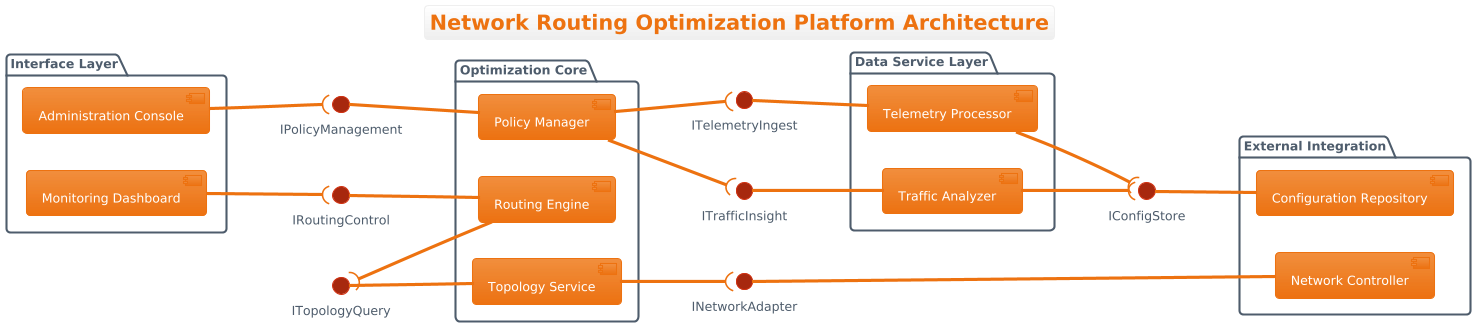
Below is the complete source code for the Network Routing Optimization Platform architecture. You can copy this code directly into the VPasCode editor to render the diagram, adjust themes, or export it for your documentation.
@startuml
!theme aws-orange
left to right direction

title Network Routing Optimization Platform Architecture

/'
This component diagram models the architecture of a Network Routing Optimization Platform designed to dynamically compute and manage optimal data paths across large-scale network infrastructures. The system ingests real-time telemetry, traffic patterns, and topology changes to feed a routing engine that generates efficient forwarding decisions. It also exposes APIs for network administrators to configure policies and visualize routing states. The architecture is organized into four logical tiers: Interface Layer, Optimization Core, Data Service Layer, and External Integration Layer, ensuring clear separation of concerns and modular scalability.
'/

package "Interface Layer" {
    component "Administration Console" as AdminConsole
    component "Monitoring Dashboard" as Dashboard
}

package "Optimization Core" {
    component "Routing Engine" as RoutingEngine
    component "Policy Manager" as PolicyManager
    component "Topology Service" as TopologyService
}

package "Data Service Layer" {
    component "Telemetry Processor" as TelemetryProcessor
    component "Traffic Analyzer" as TrafficAnalyzer
}

package "External Integration" {
    component "Network Controller" as NetController
    component "Configuration Repository" as ConfigRepo
}

' Provided interfaces (ball on the left)
interface "IRoutingControl" as IRoutingControl
interface "IPolicyManagement" as IPolicyMgmt
interface "ITopologyQuery" as ITopologyQuery
interface "ITelemetryIngest" as ITelemetryIngest
interface "ITrafficInsight" as ITrafficInsight
interface "INetworkAdapter" as INetworkAdapter
interface "IConfigStore" as IConfigStore

' Required interfaces (socket on the right)
AdminConsole --( IPolicyMgmt
Dashboard --( IRoutingControl
RoutingEngine --( ITopologyQuery
PolicyManager --( ITelemetryIngest
PolicyManager --( ITrafficInsight
TopologyService --( INetworkAdapter
TelemetryProcessor --( IConfigStore
TrafficAnalyzer --( IConfigStore

' Provided interfaces assigned to components
IRoutingControl -- RoutingEngine
IPolicyMgmt -- PolicyManager
ITopologyQuery -- TopologyService
ITelemetryIngest -- TelemetryProcessor
ITrafficInsight -- TrafficAnalyzer
INetworkAdapter -- NetController
IConfigStore -- ConfigRepo

@endumlStep-by-Step Architectural Walkthrough
Phase 1: Canvas Configuration & Layout Directives
Every PlantUML diagram begins with setup instructions that define the rendering engine’s behavior. In this section, we establish the global theme and the flow direction of the diagram. We start with @startuml to initialize the diagram block. Immediately following, we apply the !theme aws-orange directive. This applies a consistent color palette inspired by AWS branding, giving the diagram a professional, modern look without manual styling of every element.
Next, we set the layout direction using left to right direction. This is crucial for component diagrams in telecommunications, where data flows often progress from left to right (e.g., input to processing to output). This directive ensures that the packages and components align horizontally, making the architecture easier to scan. Without this, PlantUML defaults to a top-down layout, which might not suit the specific reading flow of your system documentation.
Phase 2: Declaring Core Entities, Actors, and Boundaries
Once the canvas is set, we define the structural boundaries using package blocks. This is where we group components logically. We create four distinct packages: “Interface Layer”, “Optimization Core”, “Data Service Layer”, and “External Integration”. This packaging strategy enforces the separation of concerns principle, ensuring that the user-facing tools are distinct from the core logic and data storage.
Inside each package, we declare components using the component keyword. For example, in the “Optimization Core”, we define the RoutingEngine, PolicyManager, and TopologyService. We use the as keyword to assign short aliases (like RoutingEngine) to the component names. These aliases are used later to reference the components in interface connections, keeping the code concise and readable. This phase establishes the “who” and “where” of the architecture.
Phase 3: Mapping Data Flows & Key Interactions
The heart of a component diagram lies in the interface definitions. We first declare the interfaces themselves using the interface keyword. For instance, interface "IRoutingControl" as IRoutingControl defines a contract named IRoutingControl. This acts as a placeholder for the functionality the component will provide or consume.
Next, we connect components to interfaces using specific arrow notations. To indicate a Required Interface (a socket), we use the syntax --(. For example, AdminConsole --( IPolicyMgmt means the Administration Console requires the IPolicyManagement interface to function. The parenthesis is on the right side, visually resembling a socket. Conversely, to indicate a Provided Interface (a ball), we use -- connecting the interface to the component, such as IPolicyMgmt -- PolicyManager. This explicitly shows that the PolicyManager provides the IPolicyManagement functionality. This ball-and-socket convention is standard in UML and is critical for understanding dependency direction.
Phase 4: Grouping, Annotations & Visual Polish
To finalize the diagram, we add metadata that provides context without cluttering the visual structure. We use the title directive to set the main heading of the diagram. Below the title, we insert a comment block using /' and '/. This block contains a narrative description of the system, explaining the problem context and the architecture’s purpose. This text is visible in the rendered diagram or generated documentation, serving as an immediate summary for stakeholders. Finally, we close the diagram with @enduml to signal the end of the code block.
Syntax & Keyword Deep Dive
Understanding the specific PlantUML syntax used in this diagram is essential for replicating this pattern in your own projects. Below is a breakdown of the key keywords and conventions utilized.
package: Defines a logical grouping of components. It helps manage complexity by clustering related elements, such as the “Optimization Core”.component: Represents a modular part of the system, such as a microservice or a library. It is the primary building block of the architecture.interface: Defines a contract of functionality. It separates the “what” (the interface) from the “who” (the component).--(: This arrow notation connects a component to a required interface (the socket). The parenthesis indicates consumption.--: This arrow notation connects an interface to a provided interface (the ball). It indicates provision./'and'/: These delimiters create a multi-line comment block. Unlike single-line comments ('), these allow for rich text descriptions within the diagram.!theme: A directive to apply a predefined visual theme to the entire diagram, ensuring consistent styling.
Best Practices & Pitfalls to Avoid
When modeling complex telecommunications systems, adhering to best practices ensures your diagrams remain maintainable and readable.
1. Maintain Interface Abstraction: Do not expose internal implementation details within interfaces. An interface should represent a contract (e.g., IRoutingControl), not the method signatures inside the component. This keeps the diagram focused on the architectural level rather than the code level.
2. Avoid Circular Dependencies: While PlantUML allows you to draw circular connections, in a healthy architecture, components should not depend on each other in a loop. Ensure that your provided and required interfaces create a logical flow of data, typically from the Interface Layer down to the Data Service Layer.
3. Use Consistent Naming Conventions: Prefix interfaces with I (e.g., ITelemetryIngest) to distinguish them clearly from components. This visual cue helps readers quickly identify where dependencies lie.
4. Keep Diagrams Modular: If a diagram becomes too crowded, consider splitting it into multiple views. For instance, separate the “Control Plane” from the “Data Plane” if the interaction complexity grows too high for a single view.
Try It Yourself with VPasCode
Architect Scalable Network Systems Faster with VPasCode
Instantly render, customize, and export your Network Routing Optimization Platform diagrams in the browser without installing any tools.