


In the complex realm of government land administration, data integrity is not merely a technical requirement; it is the foundation of legal certainty and public trust. A land registry system must seamlessly bridge the gap between physical geography and legal ownership, ensuring that every square meter of land has a precise digital twin and a clear chain of title. When architects design these systems, they face the challenge of modeling intricate relationships: a single property might span multiple cadastral parcels, a title deed can have multiple co-owners, and every transfer of ownership must be immutable and traceable for audit purposes.
Traditional hand-drawn diagrams often fail to capture the rigorous cardinalities and data types required for such systems, leading to implementation errors in the database layer. Diagram-as-code approaches, specifically using PlantUML, offer a solution by allowing architects to define the schema in a versioned, text-based format that can be instantly rendered and validated. By leveraging VPasCode, a free web-based diagram editor, developers can prototype these complex government-grade ERDs in real-time, ensuring that the logical structure of the database—handling everything from spatial geometry to legal transfer histories—is robust before a single line of SQL is written.
Understanding the Model: Purpose, Scope & Problem Framing
This tutorial focuses on the design of a Land Registry Entity-Relationship Diagram (ERD), a critical component for modern cadastral management systems. The diagram serves as the blueprint for a database that manages the lifecycle of real estate assets, from the initial cadastral survey of a parcel of land to the final recording of a title deed transfer.
Diagram Abstraction & Representation
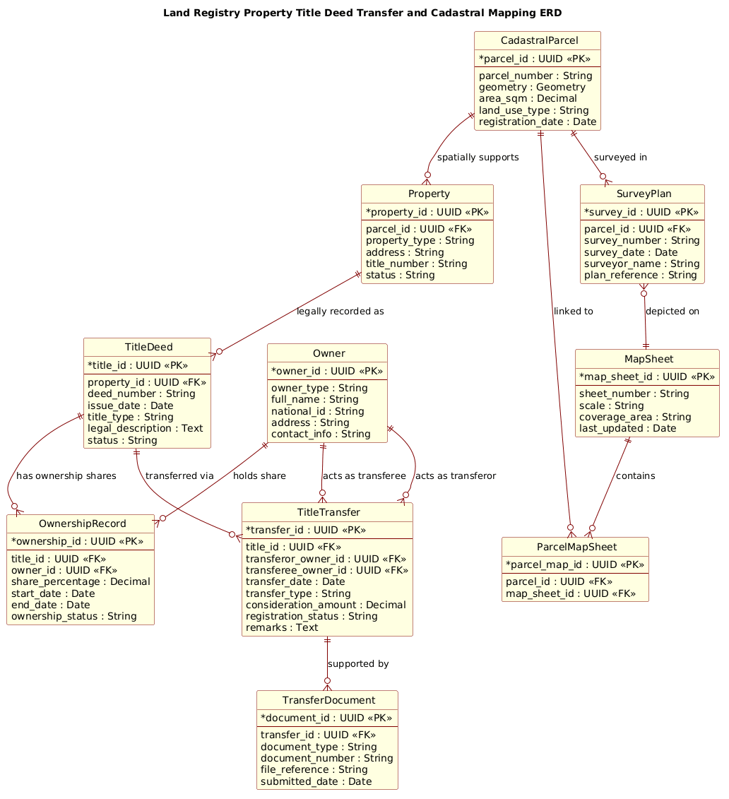
In this context, the ERD abstracts the physical world into structured data entities. The CadastralParcel entity represents the physical land, storing spatial coordinates and area metrics. The Property entity acts as a legal wrapper around the physical land, defining its address and status. The TitleDeed represents the legal instrument of ownership, while OwnershipRecord tracks the specific individuals or entities holding rights to that title. Crucially, the TitleTransfer entity captures the dynamic history of ownership changes, ensuring a complete audit trail of who sold to whom, when, and for what consideration.
Target Domain Scope & Scenario
The scope of this model is strictly limited to the core transactional and spatial data required for a government land registry. It intentionally excludes peripheral systems like tax assessment engines or mortgage banking integrations to maintain clarity. The scenario covers the full lifecycle: a parcel is surveyed, a property is created, a title is issued, owners are registered, and the title is subsequently transferred. The inclusion of SurveyPlan and MapSheet entities highlights the critical link between the legal record and the spatial map, ensuring that the digital record aligns with official cartographic data.
Key Takeaways & Educational Insights
By building this diagram, readers will gain insights into modeling one-to-many relationships (e.g., a parcel supporting multiple properties), many-to-many relationships resolved through junction tables (e.g., multiple owners sharing a title), and the importance of audit fields like registration_status and transfer_date. You will learn how to structure a database that enforces referential integrity while remaining flexible enough to handle complex ownership scenarios common in government land administration.
Complete Diagram & Full Source Code
Below is the finalized Entity-Relationship Diagram for the Land Registry system. This model demonstrates a clean separation between spatial data (parcels, maps) and legal data (titles, deeds, transfers), linked through precise foreign key relationships.
@startuml
!include https://static.visual-paradigm.com/web/resources/plantuml-stdlib/themes/rose.puml

title Land Registry Property Title Deed Transfer and Cadastral Mapping ERD

/'
Context:
This diagram models the core data structures used by a land registry system to manage
cadastral parcels, property titles, registered owners, and the legal transfer of title
deeds. The cadastral mapping component links spatial parcel records to administrative
and legal property records, while the transfer component captures the history of
ownership changes, supporting traceability, validation, and reporting.
'/

entity "CadastralParcel" as parcel {
  * parcel_id : UUID <<PK>>
  --
  parcel_number : String
  geometry : Geometry
  area_sqm : Decimal
  land_use_type : String
  registration_date : Date
}

entity "Property" as property {
  * property_id : UUID <<PK>>
  --
  parcel_id : UUID <<FK>>
  property_type : String
  address : String
  title_number : String
  status : String
}

entity "TitleDeed" as title {
  * title_id : UUID <<PK>>
  --
  property_id : UUID <<FK>>
  deed_number : String
  issue_date : Date
  title_type : String
  legal_description : Text
  status : String
}

entity "Owner" as owner {
  * owner_id : UUID <<PK>>
  --
  owner_type : String
  full_name : String
  national_id : String
  address : String
  contact_info : String
}

entity "OwnershipRecord" as ownership {
  * ownership_id : UUID <<PK>>
  --
  title_id : UUID <<FK>>
  owner_id : UUID <<FK>>
  share_percentage : Decimal
  start_date : Date
  end_date : Date
  ownership_status : String
}

entity "TitleTransfer" as transfer {
  * transfer_id : UUID <<PK>>
  --
  title_id : UUID <<FK>>
  transferor_owner_id : UUID <<FK>>
  transferee_owner_id : UUID <<FK>>
  transfer_date : Date
  transfer_type : String
  consideration_amount : Decimal
  registration_status : String
  remarks : Text
}

entity "TransferDocument" as doc {
  * document_id : UUID <<PK>>
  --
  transfer_id : UUID <<FK>>
  document_type : String
  document_number : String
  file_reference : String
  submitted_date : Date
}

entity "SurveyPlan" as survey {
  * survey_id : UUID <<PK>>
  --
  parcel_id : UUID <<FK>>
  survey_number : String
  survey_date : Date
  surveyor_name : String
  plan_reference : String
}

entity "MapSheet" as mapsheet {
  * map_sheet_id : UUID <<PK>>
  --
  sheet_number : String
  scale : String
  coverage_area : String
  last_updated : Date
}

entity "ParcelMapSheet" as parcel_map {
  * parcel_map_id : UUID <<PK>>
  --
  parcel_id : UUID <<FK>>
  map_sheet_id : UUID <<FK>>
}

parcel ||--o{ property : "spatially supports"
property ||--o{ title : "legally recorded as"
title ||--o{ ownership : "has ownership shares"
owner ||--o{ ownership : "holds share"
title ||--o{ transfer : "transferred via"
owner ||--o{ transfer : "acts as transferor"
owner ||--o{ transfer : "acts as transferee"
transfer ||--o{ doc : "supported by"
parcel ||--o{ survey : "surveyed in"
survey }o--|| mapsheet : "depicted on"
parcel ||--o{ parcel_map : "linked to"
mapsheet ||--o{ parcel_map : "contains"

@endumlStep-by-Step Architectural Walkthrough
Phase 1: Canvas Configuration & Layout Directives
The first step in building a professional ERD in PlantUML is setting the stage. We begin by including the rose.puml theme, which provides a sophisticated, enterprise-grade visual style suitable for government documentation. This theme automatically handles the rendering of entity boxes, relationship lines, and typography, ensuring the diagram looks polished without manual CSS tweaking.
Additionally, we define a title directive to provide a clear, semantic label for the diagram. This is crucial for documentation libraries where diagrams are referenced by ID. The comment block (/’ … /’) is then inserted to provide immediate context for any stakeholder reading the code, describing the scope of the land registry system without cluttering the visual model.
Phase 2: Declaring Core Entities, Actors, and Boundaries
Next, we define the fundamental building blocks of the system using the entity directive. In this phase, we create the CadastralParcel and Property entities. The parcel entity focuses on the physical land, storing attributes like geometry (for GIS integration) and area_sqm. The property entity acts as the legal interface, linking back to the parcel via a foreign key (parcel_id).
We then introduce the legal entities: TitleDeed and Owner. The title entity captures the specific legal instrument, while owner captures the human or corporate entity holding the rights. Notice the use of UUID as the primary key type; this is a best practice for distributed systems and government databases to ensure unique, non-guessable identifiers across different jurisdictions.
Phase 3: Mapping Data Flows & Key Interactions
The heart of this ERD lies in the relationships that connect these entities. We start with the spatial link: parcel ||--o{ property. This denotes that one parcel can support zero or many properties (e.g., a large estate subdivided into multiple units). We then link property to title, establishing that a property legally records a specific title deed.
The most complex interaction is the OwnershipRecord. Since a single title can have multiple owners (joint tenancy), and an owner can hold multiple titles, we cannot link them directly. Instead, we create the ownership entity as a junction table. It links title_id and owner_id, allowing us to store additional data like share_percentage and ownership_status. This pattern is essential for modeling many-to-many relationships in a relational database.
Phase 4: Grouping, Annotations & Visual Polish
The final phase involves modeling the transactional history and spatial mapping. We introduce the TitleTransfer entity, which records every change in ownership. It references both the transferor_owner_id and transferee_owner_id, creating a complete audit trail of who gave the title to whom. We also include TransferDocument to link physical or digital files to the transfer event.
Finally, we address the cadastral mapping aspect. The SurveyPlan links to a parcel, and the MapSheet entity represents the official map. The ParcelMapSheet junction table ensures that a single parcel can be displayed across multiple map sheets (e.g., a boundary crossing two sheets) and that a single map sheet can contain multiple parcels. The use of specific relationship arrows (like ||--o{ for mandatory one to optional many) visually communicates the business rules of the land registry system.
Syntax & Keyword Deep Dive
To fully leverage PlantUML for ERD modeling, it is essential to understand the specific syntax used in this diagram. The following keywords and conventions define the structure and relationships of the land registry system.
entity: This keyword defines a database table or class. It is followed by the entity name (e.g.,"CadastralParcel") and an alias (e.g.,as parcel) used for referencing in relationships. Inside the braces, attributes are listed with their data types (e.g.,UUID,String,Date).PKandFKStereotypes: The<(Primary Key) and> <(Foreign Key) markers are critical for database architects. They visually distinguish the unique identifier of a table from the columns that link to other tables, ensuring referential integrity is clear at a glance.> ||--o{Relationship Arrow: This is a specific PlantUML ERD notation. The double bar||indicates “mandatory one,” and the crow’s footo{indicates “optional many.” For example,parcel ||--o{ propertymeans every property must belong to exactly one parcel, but a parcel can exist without any properties (or have many)./' ... /'Comment Block: This syntax allows for multi-line comments that are rendered as a text block within the diagram. It is used here to provide a high-level context description of the system’s purpose, which is invaluable for documentation but does not affect the rendering logic.!includeDirective: This command loads external resources, such as therose.pumltheme. It allows for consistent styling across multiple diagrams and keeps the main code clean by separating visual definitions from structural data.
Best Practices & Pitfalls to Avoid
When modeling complex government systems like land registries, adhering to best practices ensures the diagram remains maintainable and accurate.
- Use Descriptive Aliases: Avoid generic aliases like
e1ore2. Instead, use semantic aliases likeas parceloras title. This makes the relationship lines (e.g.,parcel ||--o{ property) readable and self-documenting. - Separate Spatial from Legal Data: As seen in this diagram, keep the physical attributes (geometry, area) in the
CadastralParcelentity and the legal attributes (title number, deed number) in thePropertyorTitleDeedentities. Mixing these concerns can lead to a bloated, hard-to-maintain table structure. - Explicitly Model Junction Tables: Never hide many-to-many relationships. Always create an explicit entity (like
OwnershipRecord) to hold the relationship and any additional attributes (like share percentage). This is a common pitfall in ERD design that leads to database normalization issues. - Standardize Data Types: Ensure consistency in data types across the diagram. For example, use
UUIDfor all primary keys andDatefor all temporal fields. This consistency is vital when generating SQL scripts from the diagram.
Start Building Land Registry ERDs Faster with VPasCode
Instantly visualize and refine your complex cadastral and title deed database schemas with VPasCode’s free, browser-based PlantUML editor—no installation required.