


Welcome to another technical masterclass from the experts at Visual Paradigm! When designing embedded systems or complex software workflows, visualizing state transitions is crucial. Today, I am going to walk you through my exact thought process for building a clean, professional state machine diagram—specifically modeling a microwave oven—using PlantUML inside our diagram-as-code tool.
Whether you are looking for a reliable PlantUML editor or a free PlantUML editor to streamline your documentation, writing code to generate diagrams gives you ultimate version control and precision. Let’s dive right into how I constructed this masterpiece from scratch.
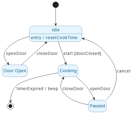
Step 1: Establishing the Foundational Structure and Theme
When I first open up our free PlantUML editor, my primary goal is to establish a consistent visual hierarchy before dropping in a single state. Default diagram styles can often look cluttered or dated, so I like to inject custom skin parameters right at the beginning.
Here is how I set up the canvas configuration:
- Diagram Type: I explicitly declare
skinparam vpDiagramType StateDiagramto align the canvas rendering context. - Typography: I set a clean, readable font size of
14and a dark neutral font color (#333333) to ensure high contrast. - Clean Canvas: I disable shadows (
skinparam shadowing false) and enforce a crisp, flat white background with sharp borders. - State Styling: I give individual states a distinct professional look by assigning a soft blue background (
#E6F5FF) paired with a deep navy border and text color (#005073).
Why this approach? By handling global themes up front, I don’t have to style individual boxes later. It keeps the core logic code clean and guarantees uniform branding across all technical documents.
Step 2: Defining States and System Boundaries
With the styling bedrock locked in, my next step is to map out the core components of our system—in this case, the operational states of a microwave. I hide empty descriptions to keep the rendering sleek. Then, I declare my entry/exit anchor points and the primary states: Idle, Door Open, Cooking, and Paused.
Here is how I define the state entities in code:
hide empty description

state initialstate01 <<start>>
state "Idle" as Idle
state "Door Open" as DoorOpen
state "Cooking" as Cooking
state "Paused" as Paused
state finalstate01 <<start>>
Notice how I use clear, human-readable aliases. Wrapping labels in quotes (like state "Door Open" as DoorOpen) lets me use natural phrasing in the visual diagram while maintaining concise, camel-case identifiers in my script logic.
Step 3: Mapping State Transitions and Guard Conditions
Now comes the heart of behavioral modeling: connecting the states with meaningful transitions, triggers, and guards. In a real-world microwave workflow, actions depend strictly on physical events (like opening a door or pushing start) and internal logic (like whether the door is closed or the timer expired).
I map out the transition flow chronologically:
- Idle State Behavior: When the microwave is sitting idle, entering the state triggers a clock reset (
Idle : entry / resetCookTime). Users can open the door (Idle --> DoorOpen : openDoor) or initiate cooking, provided the safety guard condition is met (Idle --> Cooking : start [doorClosed]). - Interruption Handling: If someone opens the door mid-cooking, the system shifts immediately to a paused state (
Cooking --> Paused : openDoor), which can either resume heating once closed (Paused --> Cooking : closeDoor) or cancel altogether back to idle (Paused --> Idle : cancel). - Completion: Once the countdown finishes, the system fires a beep and terminates at the final state (
Cooking --> finalstate01 : timerExpired / beep).
Step 4: Putting It All Together
Finally, I connect the initial bootstrap state to our primary flow and close out the block. Here is the complete, cohesive PlantUML script that powers our final diagram:
@startuml
skinparam vpDiagramType StateDiagram
skinparam defaultFontSize 14
skinparam defaultFontColor #333333
skinparam shadowing false
skinparam {
  ArrowColor #333333
  ArrowFontColor #333333
  BackgroundColor #FFFFFF
  BorderColor #333333

  State {
    BorderColor #005073
    BackgroundColor #E6F5FF
    FontColor #005073
  }
}
hide empty description

state initialstate01 <<start>>
state "Idle" as Idle
state "Door Open" as DoorOpen
state "Cooking" as Cooking
state "Paused" as Paused
state finalstate01 <<end>>

Idle : entry / resetCookTime
Idle --> DoorOpen : openDoor
DoorOpen --> Idle : closeDoor
Idle --> Cooking : start [doorClosed]
Cooking --> Paused : openDoor
Paused --> Cooking : closeDoor
Cooking --> finalstate01 : timerExpired / beep
Paused --> Idle : cancel

initialstate01 --> Idle
@endumlBring Your Diagrams to Life with VPasCode
Writing diagram code is fast, precise, and infinitely maintainable. When you are ready to experiment with your own architectures, state machines, or sequence flows, you don’t need heavy desktop installations.
Head over to VPasCode Editor to experience real-time rendering, automatic format detection, and instant SVG/PNG exports completely free!