Building a Professional Warehouse Management Use Case Diagram with PlantUML and VPasCode
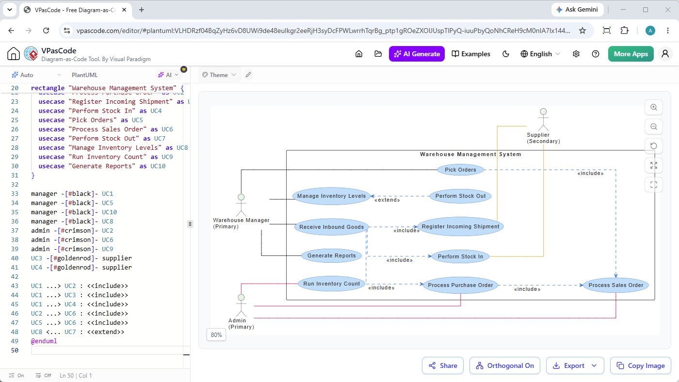
When designing complex enterprise applications like a Warehouse Management System (WMS), visualizing system boundaries, actors, and use cases is essential. As an expert technical instructor at Visual Paradigm, I frequently get asked how to create clean, presentation-ready architectural diagrams without getting bogged down by clunky drag-and-drop tools. In this masterclass tutorial, I will walk you through my exact thought process for building a comprehensive WMS use case diagram using PlantUML inside the free PlantUML editor, VPasCode.
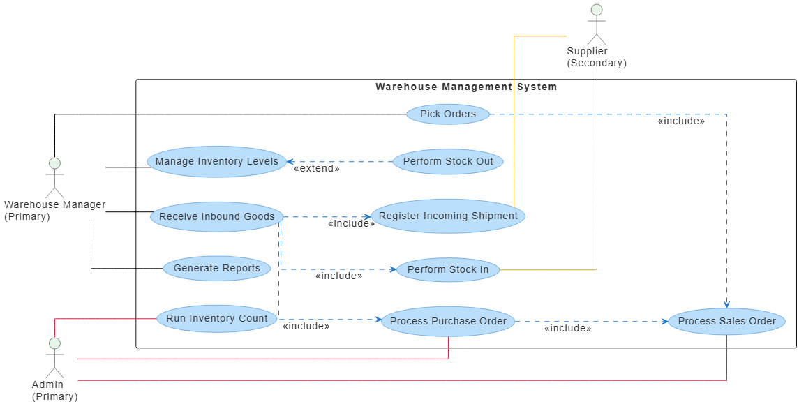
Here is a preview of the final diagram we will be building together:
Final Use Case Diagram for Warehouse Management System
1. Setting Up Global Styles and Foundational Structure
Whenever I start a new diagram-as-code project, my first priority is establishing a consistent visual hierarchy and aesthetic. Standard diagrams can often look cluttered, so I like to override default styles early to ensure clean lines, readable typography, and structured color palettes.
I start by configuring orthogonal connectors (linetype ortho) to keep all connecting lines clean, horizontal, or vertical—avoiding messy diagonal lines crossing over text. Then, I set up custom color-coding for actors and use cases to distinguish primary actors, secondary entities, and internal system boundaries immediately.
@startuml
skinparam linetype ortho
skinparam defaultFontSize 14
skinparam defaultFontColor #333333
skinparam vpDiagramType UseCaseDiagram
skinparam actor {
  BackgroundColor #E8F5E9
}
skinparam usecase {
  BackgroundColor #BBDEFB
  BorderColor #1976D2
  ArrowColor #1976D2
}

left to right direction
2. Defining System Actors and System Boundaries
Next, I need to define the boundaries of the system and identify who interacts with it. In our warehouse management scenario, we have three distinct actors:
Warehouse Manager: A primary actor responsible for daily operations, inventory levels, and stock movements.
Admin: A primary actor managing high-level inventory counts, purchase orders, and system reports.
Supplier: A secondary actor who triggers inbound shipments and stock-ins from an external perspective.
I wrap all internal system functionalities inside a rectangle container representing the Warehouse Management System. This cleanly separates internal use cases from external actors.
actor "Warehouse Manager\n(Primary)" as manager
actor "Admin\n(Primary)" as admin
actor "Supplier\n(Secondary)" as supplier

rectangle "Warehouse Management System" {
  usecase "Receive Inbound Goods" as UC1
  usecase "Process Purchase Order" as UC2
  usecase "Register Incoming Shipment" as UC3
  usecase "Perform Stock In" as UC4
  usecase "Pick Orders" as UC5
  usecase "Process Sales Order" as UC6
  usecase "Perform Stock Out" as UC7
  usecase "Manage Inventory Levels" as UC8
  usecase "Run Inventory Count" as UC9
  usecase "Generate Reports" as UC10
}
3. Mapping Actor Associations and Color Coding
To make the diagram intuitively scannable, I map out associations between actors and their respective use cases. I apply color-coded links corresponding to each actor type: neutral black for warehouse managers, crimson for administrators, and goldenrod for suppliers. This technique drastically reduces cognitive load when reviewers analyze system permissions.
4. Establishing Use Case Relationships (Includes and Extends)
The final step is defining how internal use cases relate to one another using dependency arrows. I use <<include>> relationships to show mandatory sub-processes (such as receiving inbound goods requiring shipment registration and stock-in logging) and <<extend>> relationships for optional or conditional behaviors like managing inventory levels during stock-outs.
Building this diagram inside VPasCode gives you several distinct advantages over traditional desktop drawing tools:
Real-Time Rendering: As you type or tweak your PlantUML code, the visual preview updates instantly.
Automatic Format Detection: You never have to manually specify your syntax engine—VPasCode detects PlantUML, Mermaid, and other formats on the fly.
Free Export Options: Download your finished architecture diagrams as high-resolution PNGs, scalable SVGs, or share them instantly with your team via secure URLs.