


In the rapidly evolving landscape of fintech and traditional banking, the precision of system requirements modeling is paramount. A Core Banking System serves as the backbone of financial operations, handling critical functions such as account management, fund transfers, and loan processing. For software architects and business analysts, translating these complex workflows into a visual blueprint is essential for stakeholder alignment and development clarity.
Visual modeling is not merely about drawing; it is about defining system boundaries and interactions. When utilizing PlantUML within VPasCode, architects gain the ability to treat diagrams as living code. This approach ensures that documentation remains versioned alongside the actual software, reduces ambiguity in financial logic, and accelerates the prototyping phase. By adopting a diagram-as-code methodology, teams can validate actor interactions and system capabilities before a single line of backend code is written.
Understanding the Model: Purpose, Scope & Problem Framing
Diagram Abstraction & Representation
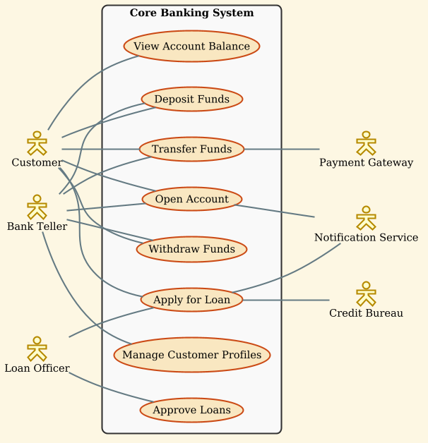
A Use Case Diagram is the primary tool for capturing functional requirements from a user’s perspective. Unlike flowcharts that detail the step-by-step logic, a Use Case diagram focuses on who does what. In this model, Actors represent external entities (human roles or external systems) that interact with the system, while Use Cases (ellipses) represent the specific functional goals or services the system provides.
This diagram specifically models the Core Banking System. It abstracts away the internal database queries or API endpoints to focus on the business value delivered to the bank’s customers and employees.
Target Domain Scope & Scenario
The scope of this model covers the primary transactional and administrative workflows of a banking institution. It explicitly defines the boundaries between:
- Customer-Facing Operations: Self-service actions like deposits, withdrawals, and balance inquiries.
- Employee Operations: Manual interventions handled by tellers and loan officers.
- External Integrations: Critical dependencies on third-party services such as Payment Gateways and Credit Bureaus.
By isolating these interactions, the diagram clarifies which responsibilities belong to the internal system versus external partners.
Key Takeaways & Educational Insights
By studying this model, readers will gain insight into:
- Actor Differentiation: How to distinguish between a retail customer and a bank employee based on their permitted use cases.
- System Boundaries: How to encapsulate core logic within a rectangle to define the system perimeter.
- Dependency Mapping: How to visualize indirect dependencies (e.g., how a loan application triggers a credit check).
Complete Diagram & Full Source Code
Before diving into the construction, visualize the final architecture. This diagram captures the full scope of the Core Banking System interactions using the sunlust theme for a professional, modern aesthetic.
@startuml
!theme sunlust
left to right direction
skinparam actorStyle hollow

skinparam rectangle {
    BackgroundColor #F9F9F9
    BorderColor #333333
}

actor "Customer" as customer
actor "Bank Teller" as teller
actor "Loan Officer" as loan_officer

rectangle "Core Banking System" {
  usecase "Open Account" as uc1
  usecase "Deposit Funds" as uc2
  usecase "Withdraw Funds" as uc3
  usecase "Transfer Funds" as uc4
  usecase "Apply for Loan" as uc5
  usecase "View Account Balance" as uc6
  usecase "Manage Customer Profiles" as uc7
  usecase "Approve Loans" as uc8
}

actor "Payment Gateway" as payment_gateway
actor "Credit Bureau" as credit_bureau
actor "Notification Service" as notification_service

customer -- uc1
customer -- uc2
customer -- uc3
customer -- uc4
customer -- uc5
customer -- uc6

teller -- uc1
teller -- uc2
teller -- uc3
teller -- uc4
teller -- uc7

loan_officer -- uc5
loan_officer -- uc8

uc4 -- payment_gateway
uc5 -- credit_bureau
uc1 -- notification_service
uc5 -- notification_service
@endumlStep-by-Step Architectural Walkthrough
Building a professional diagram requires a structured approach. We will construct this Core Banking System model in four distinct phases.
Phase 1: Canvas Configuration & Layout Directives
The foundation of any PlantUML diagram lies in its configuration. We begin by setting the rendering theme and the layout direction to ensure the diagram fits well on screen and matches the visual branding of the documentation.
We use the !theme sunlust directive to apply a modern, high-contrast color palette that is easy to read. The left to right direction directive ensures the diagram flows horizontally, which is often more natural for wide system boundary diagrams.
!theme sunlust
left to right direction
skinparam actorStyle hollow
Phase 2: Declaring Core Entities, Actors, and Boundaries
Next, we define the participants. In PlantUML, Actors represent the users or external systems. We assign aliases (e.g., customer) to keep the relationship lines clean and readable. We also define the system boundary using a Rectangle to encapsulate the internal use cases.
actor "Customer" as customer
actor "Bank Teller" as teller

rectangle "Core Banking System" {
  usecase "Open Account" as uc1
  usecase "Deposit Funds" as uc2
}
Note the use of skinparam rectangle to customize the background color and border, ensuring the system boundary stands out clearly against the white background.
Phase 3: Mapping Data Flows & Key Interactions
With actors and use cases declared, we now map the relationships. In a Use Case diagram, a simple line (--) represents an association. We connect the Customer to the standard banking functions like deposits and withdrawals.
customer -- uc2
customer -- uc3
customer -- uc4
For external dependencies, we connect use cases to external actors. For instance, transferring funds (uc4) requires interaction with a Payment Gateway. This highlights that the Core Banking System is not an island but part of a larger ecosystem.
uc4 -- payment_gateway
uc5 -- credit_bureau
Phase 4: Grouping, Annotations & Visual Polish
The final phase involves refining the visual hierarchy. We ensure that all internal use cases are grouped within the rectangle block, while external actors remain outside. This visual separation is crucial for understanding system boundaries. We also add specific styling parameters to ensure the Loan Officer interactions are distinct from the Teller interactions.
skinparam rectangle {
    BackgroundColor #F9F9F9
    BorderColor #333333
}
This styling ensures the system box is subtle yet defined, allowing the relationships (lines) to take visual precedence.
Syntax & Keyword Deep Dive
Understanding the specific syntax of PlantUML allows you to customize and extend this diagram for other financial systems. Below are the key keywords used in this tutorial.
!theme: A directive that loads a predefined color and style set. In this case,sunlustprovides a professional financial aesthetic.skinparam: Used to override default styling for specific elements like actors or rectangles. It allows fine-tuning of colors and borders.actor: Defines a user or external system. The syntaxactor "Label" as aliasallows for custom names and shorter references in relationships.rectangle: Defines a system boundary. Everything inside the curly braces{}is considered part of that system’s internal functionality.usecase: Represents a specific function or goal. Using aliases (e.g.,as uc1) prevents clutter when drawing multiple connections.--: The association operator. It draws a line between two entities. In this diagram, it signifies that the actor can perform the use case or that the use case relies on the external actor.
Best Practices & Pitfalls to Avoid
To maintain high-quality architectural documentation, follow these guidelines when modeling financial systems:
- Keep Use Cases Atomic: Avoid combining multiple actions into one use case. For example, separate “Deposit Funds” from “Withdraw Funds” rather than combining them into “Manage Cash”.
- Respect System Boundaries: Ensure external dependencies (like Credit Bureaus) are placed outside the main rectangle to accurately reflect system architecture.
- Use Meaningful Aliases: Always assign aliases (e.g.,
as customer) to actors and use cases. This keeps the relationship lines clean and reduces code length. - Limit Actor Complexity: If an actor has too many connections, consider splitting them into specialized roles (e.g., “Retail Customer” vs. “Corporate Client”) to improve readability.
Try It Yourself with VPasCode
Start Building PlantUML Use Case Diagrams Faster with VPasCode
Instantly render, customize, and export your Core Banking System diagrams online without installing any tools or configuring local environments.