


In the high-stakes world of financial technology, clarity in system requirements is non-negotiable. A Fraud Detection System serves as the critical shield between legitimate transactions and malicious activity. However, defining the boundaries of such a system can be complex, involving multiple stakeholders ranging from end-users to backend security analysts.

Visual modeling bridges the gap between technical logic and business requirements. By using a Use Case Diagram, architects can clearly delineate who interacts with the system (actors) and what functional goals they achieve (use cases). This tutorial demonstrates how to leverage VPasCode, the free web-based PlantUML editor, to build a professional-grade fraud detection blueprint. This approach eliminates environment setup, allowing you to prototype and validate system logic instantly in the browser.
Understanding the Model: Purpose, Scope & Problem Framing
Before writing a single line of code, it is essential to understand the abstraction we are modeling.
Diagram Abstraction & Representation
A Use Case Diagram models the functional requirements of a system from the perspective of external users. It does not show internal implementation details (like database tables or API endpoints) but rather focuses on behavior. In this context:
- Actors: Represent roles that initiate actions (e.g., Customer, Fraud Analyst).
- Use Cases: Represent specific goals or functions (e.g., Submit Transaction, Review Alert).
- System Boundary: The rectangle enclosing the use cases defines what is inside the system versus what is external.
Target Domain Scope & Scenario
This diagram specifically models the Fraud Detection System within a finance industry context. The scope includes:
- Transaction Initiation: How customers and merchants submit payment data.
- Security Processing: Internal risk analysis and identity verification.
- Operational Oversight: How administrators configure rules and analysts review flagged alerts.
Key Takeaways & Educational Insights
By constructing this model, you will gain clarity on:
- Which external systems (like Payment Gateways) interact directly with the fraud engine.
- How internal dependencies (like Identity Checks) are included within broader processes.
- The separation of duties between automated systems and human analysts.
Complete Diagram & Full Source Code
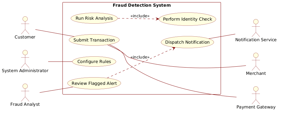
Below is the complete blueprint for the Fraud Detection System Use Case Diagram. You can view the rendered result immediately by pasting the code into the VPasCode editor.
@startuml
!include https://static.visual-paradigm.com/web/resources/plantuml-stdlib/themes/rose.puml
left to right direction

actor "Customer" as Customer
actor "Merchant" as Merchant
actor "System Administrator" as Admin

actor "Payment Gateway" as Gateway
actor "Fraud Analyst" as Analyst
actor "Notification Service" as Notifier

rectangle "Fraud Detection System" {
    usecase "Submit Transaction" as UC1
    usecase "Run Risk Analysis" as UC2
    usecase "Review Flagged Alert" as UC3
    usecase "Configure Rules" as UC4
    usecase "Perform Identity Check" as UC5
    usecase "Dispatch Notification" as UC6
}

Customer -- UC1
UC1 --- Merchant
Admin -- UC4
UC1 --- Gateway

UC2 ..> UC5 : <<include>>
UC3 ..> UC6 : <<include>>

Analyst -- UC3
UC6 -- Notifier

@endumlStep-by-Step Architectural Walkthrough
Follow this chronological guide to understand how the diagram was constructed, from theme configuration to relationship mapping.
Phase 1: Canvas Configuration & Layout Directives
The first step in any PlantUML project is setting the rendering environment. We start by defining the theme and the directional flow of the diagram.
We include the rose.puml theme to apply a consistent, professional color palette suitable for financial documentation. We also set the direction to left to right to optimize horizontal space for the actor-system-actor interactions.
!include https://static.visual-paradigm.com/web/resources/plantuml-stdlib/themes/rose.puml
left to right direction
Phase 2: Declaring Core Entities, Actors, and Boundaries
Next, we define the participants. In VPasCode, actors are declared using the actor keyword. We group the internal logic within a rectangle labeled “Fraud Detection System” to establish the system boundary.
actor "Customer" as Customer
actor "Merchant" as Merchant
actor "System Administrator" as Admin

rectangle "Fraud Detection System" {
    usecase "Submit Transaction" as UC1
    usecase "Run Risk Analysis" as UC2
    usecase "Review Flagged Alert" as UC3
    usecase "Configure Rules" as UC4
    usecase "Perform Identity Check" as UC5
    usecase "Dispatch Notification" as UC6
}
Note the use of as to assign short aliases (e.g., UC1) for cleaner relationship lines later.
Phase 3: Mapping Data Flows & Key Interactions
Now we connect the external actors to the internal use cases. Solid lines (--) indicate direct association, while dashed lines (---) indicate optional or alternative flows.
Customer -- UC1
UC1 --- Merchant
Admin -- UC4
UC1 --- Gateway
This phase establishes that Customers and Merchants initiate transactions, while Administrators manage system rules. The Payment Gateway also interacts directly with the transaction submission process.
Phase 4: Grouping, Annotations & Visual Polish
Finally, we define internal dependencies using the ..> arrow and the <<include>> stereotype. This indicates that specific sub-processes are mandatory parts of a larger use case.
UC2 ..> UC5 : <<include>>
UC3 ..> UC6 : <<include>>

Analyst -- UC3
UC6 -- Notifier
This clarifies that “Run Risk Analysis” includes “Perform Identity Check,” and “Review Flagged Alert” includes “Dispatch Notification.” The Analyst interacts with the review process, and the system notifies the external Notification Service.
Syntax & Keyword Deep Dive
Understanding the specific PlantUML syntax is crucial for maintaining and extending your diagrams.
actor: Declares a participant (human or system) that interacts with the system. Can be aliased usingas.rectangle: Defines the system boundary. Everything inside is considered part of the system’s scope.usecase: Defines a specific functional goal or action available to the actors.--(Solid Line): Represents a direct association or communication between an actor and a use case...>(Dashed Arrow): Represents a dependency relationship, often used for includes or extends.<<include>>: A stereotype indicating that one use case incorporates the behavior of another. This enforces that the included behavior is mandatory.
Best Practices & Pitfalls to Avoid
To ensure your PlantUML diagrams remain maintainable and clear, adhere to these modeling principles:
- Keep Use Cases Atomic: Ensure each use case represents a single, distinct goal. Avoid combining unrelated actions into one use case.
- Consistent Naming: Use verb-noun phrases for use cases (e.g., “Submit Transaction”) to maintain clarity across the team.
- Manage Visual Complexity: If the diagram becomes too crowded, consider splitting it into subsystem-level diagrams rather than adding more actors to one view.
- Leverage Themes: Use themes like
rose.pumlto ensure consistent styling without manually defining colors for every element.
Try It Yourself with VPasCode
Start Building PlantUML Diagrams Faster with VPasCode
Instantly preview and customize your Fraud Detection System diagrams online without installing any tools or configuration.