


Introduction: Visualizing Financial Trust in Crypto Architecture
In the high-stakes environment of cryptocurrency exchanges, clarity is not just a design preference—it is a compliance requirement. When users deposit funds into a digital wallet, they are engaging in a critical financial transaction that involves complex interactions between external blockchain networks and internal exchange ledgers. Misunderstanding this flow can lead to security vulnerabilities, financial discrepancies, or poor user experience.

Visual modeling bridges the gap between technical implementation and business logic. An Activity Diagram in PlantUML is the ideal tool for mapping these workflows. It allows architects to define the sequence of actions, decision points, and parallel processes that occur during a deposit. By using a diagram-as-code approach with VPasCode, development teams can maintain living documentation that evolves alongside the codebase.
This tutorial demonstrates how to build a professional-grade PlantUML activity diagram for a Crypto Exchange Wallet Deposit process. We will utilize swimlanes to distinguish between user actions and system processing, implement parallel flows to simulate blockchain verification, and apply conditional logic to handle confirmation thresholds. All of this is rendered instantly in the browser using VPasCode, the free web-based diagram editor.
Understanding the Model: Purpose, Scope & Problem Framing
Before diving into the syntax, it is essential to understand the architectural abstraction we are creating. This diagram models a synchronous financial transaction that relies on asynchronous blockchain confirmations.
Diagram Abstraction & Representation
An Activity Diagram represents the flow of control from one activity to another. In this context, it serves as a behavioral specification. It answers the question: “What happens from the moment a user clicks ‘Deposit’ until the funds are credited?” The diagram uses swimlanes to partition responsibility. The User lane represents external triggers and client-side actions, while the Exchange System lane represents backend services, database updates, and blockchain monitoring.
Target Domain Scope & Scenario
The scope of this model covers the core deposit workflow for a specific cryptocurrency. It intentionally excludes the user registration process or withdrawal logic to maintain focus on the deposit lifecycle. The scenario assumes the user has an external wallet and initiates a transfer to the exchange’s deposit address. The system must then validate this transfer, monitor the blockchain, and update the internal ledger.
Key Takeaways & Educational Insights
By constructing this diagram, you will gain insight into:
- Separation of Concerns: How to visually separate user interaction from backend processing using swimlanes.
- Concurrency Handling: How to model parallel tasks, such as validating transaction details while simultaneously monitoring confirmation counts.
- State Management: How to represent the transition of a transaction from
PENDINGtoCOMPLETEDbased on external conditions.
Complete Diagram & Full Source Code
Below is the complete blueprint for the Crypto Exchange Wallet Deposit process. You can view the rendered result immediately by pasting this code into the VPasCode editor.
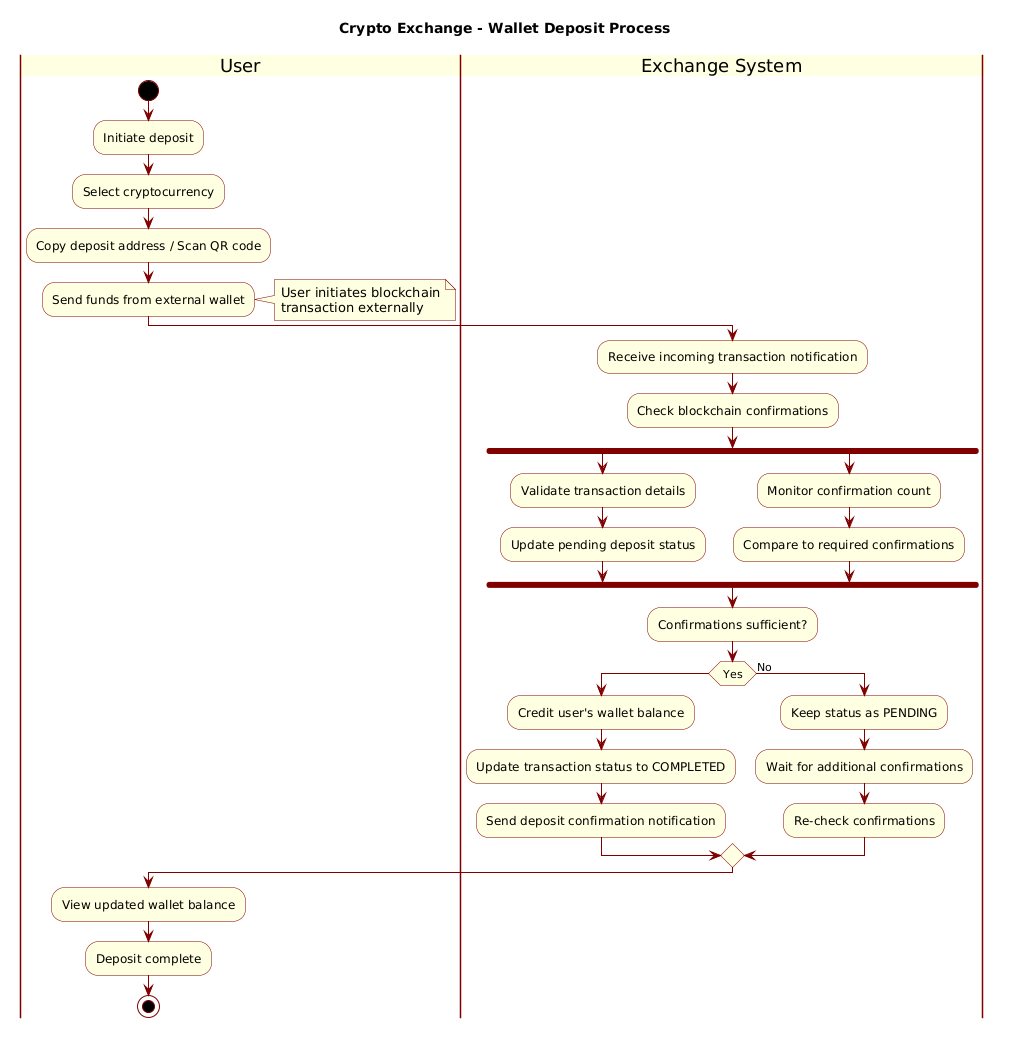
Note: The image above is a placeholder. To see the actual rendered diagram, use the code block below.
@startuml
!include https://static.visual-paradigm.com/web/resources/plantuml-stdlib/themes/rose.puml

title Crypto Exchange - Wallet Deposit Process

|User|
start
:Initiate deposit;
:Select cryptocurrency;
:Copy deposit address / Scan QR code;
:Send funds from external wallet;
note right
  User initiates blockchain
  transaction externally
end note

|Exchange System|
:Receive incoming transaction notification;
:Check blockchain confirmations;

fork
  :Validate transaction details;
  :Update pending deposit status;
fork again
  :Monitor confirmation count;
  :Compare to required confirmations;
end fork

:Confirmations sufficient?;
if (Yes) then
  :Credit user's wallet balance;
  :Update transaction status to COMPLETED;
  :Send deposit confirmation notification;
else (No)
  :Keep status as PENDING;
  :Wait for additional confirmations;
  :Re-check confirmations;
endif

|User|
:View updated wallet balance;
:Deposit complete;
stop
@endumlStep-by-Step Architectural Walkthrough
Building this diagram in VPasCode is an iterative process. We will break down the construction into four logical phases to ensure clarity and maintainability.
Phase 1: Canvas Configuration & Layout Directives
Every PlantUML diagram begins with setup directives. We start by declaring the language and including the visual theme.
In the code above, we use @startuml to initialize the diagram. The !include directive loads the rose.puml theme, which provides a consistent, professional color palette suitable for financial documentation. This ensures the diagram looks polished without requiring manual styling for every element.
@startuml
!include https://static.visual-paradigm.com/web/resources/plantuml-stdlib/themes/rose.puml

title Crypto Exchange - Wallet Deposit Process
We also define the title directive. This renders a header at the top of the diagram, providing immediate context for anyone viewing the documentation.
Phase 2: Declaring Core Entities, Actors, and Boundaries
Financial workflows require clear accountability. We achieve this using swimlanes. In PlantUML, swimlanes are defined by placing the lane name in vertical bars |Name|. This creates a vertical column that groups all activities assigned to that actor.
|User|
start
:Initiate deposit;
:Select cryptocurrency;
:Copy deposit address / Scan QR code;
:Send funds from external wallet;
Here, the |User| lane captures the initiation phase. We use the start node to mark the entry point of the workflow. Each subsequent action is represented by a rounded rectangle containing the text of the action.
Phase 3: Mapping Data Flows & Key Interactions
The core complexity of a crypto deposit lies in the blockchain verification. This requires parallel processing because validation and monitoring happen simultaneously.
|Exchange System|
:Receive incoming transaction notification;
:Check blockchain confirmations;

fork
  :Validate transaction details;
  :Update pending deposit status;
fork again
  :Monitor confirmation count;
  :Compare to required confirmations;
end fork
The fork and fork again directives create parallel branches. The system splits the flow to perform validation and monitoring concurrently. The end fork directive merges these branches back into a single flow, ensuring that both tasks must complete before proceeding.
Phase 4: Grouping, Annotations & Visual Polish
Finally, we handle decision logic and user feedback. The if statement represents the decision point regarding blockchain confirmations.
:Confirmations sufficient?;
if (Yes) then
  :Credit user's wallet balance;
  :Update transaction status to COMPLETED;
else (No)
  :Keep status as PENDING;
  :Wait for additional confirmations;
  :Re-check confirmations;
endif

:View updated wallet balance;
:Deposit complete;
stop
The if block routes the flow based on the condition. The note right annotation provides extra context without cluttering the main flow. The stop node marks the definitive end of the process.
Syntax & Keyword Deep Dive
To master PlantUML activity diagrams, you must understand the specific keywords that control flow and structure. Here is a breakdown of the critical syntax used in this tutorial.
start/stop: Defines the entry and exit points of the activity flow. Every valid diagram should begin withstartand end withstop.|Lane Name|: Creates a swimlane. This is crucial for separating responsibilities between different actors (e.g., User vs. System).fork/fork again/end fork: Enables parallel execution. Useforkto split the flow,fork againto add more parallel branches, andend forkto synchronize them back together.if/endif: Creates conditional branching. You can specify labels for thethenandelsepaths to make the logic clear.note: Adds a sticky note annotation to an activity. This is useful for adding context, warnings, or explanations without altering the flow.title: Sets the header text displayed at the top of the rendered diagram.
Best Practices & Pitfalls to Avoid
When modeling financial workflows in VPasCode, adhering to best practices ensures your diagrams remain maintainable and readable.
1. Maintain Swimlane Balance
Avoid creating swimlanes with only one or two steps. If a lane is too sparse, consider merging it with another actor or splitting the diagram into sub-processes. Balanced swimlanes improve readability.
2. Limit Branching Complexity
While fork and if are powerful, excessive nesting creates “spaghetti diagrams.” If a flow has more than three levels of conditional branching, consider breaking it into multiple diagrams linked by references.
3. Use Descriptive Labels
Never use generic labels like “Process” or “Check.” Use specific terms like “Validate Transaction Hash” or “Compare Block Height.” This makes the diagram self-documenting.
4. Leverage Themes for Consistency
Always include a theme directive (like rose.puml) to ensure your diagrams match your organization’s branding. This saves time on manual styling and looks professional.
Try It Yourself with VPasCode
Start Building PlantUML Activity Diagrams Faster with VPasCode
Design complex financial workflows instantly in your browser with zero installation, live preview, and interactive syntax testing.