


In the high-stakes environment of cryptocurrency exchanges, transaction integrity and system reliability are paramount. Every trade executed on a platform involves complex, multi-step interactions between user interfaces, order engines, liquidity pools, and financial ledgers. A single miscommunication or race condition can result in significant financial loss or regulatory non-compliance.

To mitigate these risks, architects and developers rely on visual modeling to validate system behaviors before writing a single line of production code. Sequence diagrams are particularly effective for this purpose, as they map the chronological flow of messages between system components. By using PlantUML with VPasCode, finance engineers can prototype these critical workflows instantly in the browser. This approach eliminates the friction of local environment setup, allowing teams to iterate on logic, validate error paths, and document API contracts with zero configuration.
Understanding the Model: Purpose, Scope & Problem Framing
Before diving into the syntax, it is essential to understand the architectural abstraction we are modeling. This diagram represents the lifecycle of a “Buy Order” within a cryptocurrency exchange ecosystem.
Diagram Abstraction & Representation
A sequence diagram visualizes the interaction between objects over time. In this context, it models the synchronous and asynchronous messaging required to move assets securely. We use Actors to represent human users (the Trader) and Participants to represent internal services (the Order Engine, Wallet Service). The vertical axis represents time, ensuring that every arrow drawn corresponds to a specific step in the transaction lifecycle.
Target Domain Scope & Scenario
This model focuses specifically on the order execution flow. It intentionally abstracts away background processes like user authentication or database sharding to focus on the core financial logic: validating funds, matching liquidity, and updating balances. The scenario covers both the success path (sufficient liquidity) and the failure path (insufficient liquidity or slippage), which is critical for financial auditing.
Key Takeaways & Educational Insights
By constructing this diagram, you will gain clarity on:
- System Boundaries: Clearly defining where the application ends and the ledger begins.
- Error Handling: Visualizing how the system responds when market conditions fail to meet order requirements.
- State Transitions: Tracking the movement of assets from a pending state to a committed state in the database.
Complete Diagram & Full Source Code
Below is the finished blueprint for the Cryptocurrency Purchase scenario. You can view the rendered diagram directly in the VPasCode editor to see the sunlust theme applied.
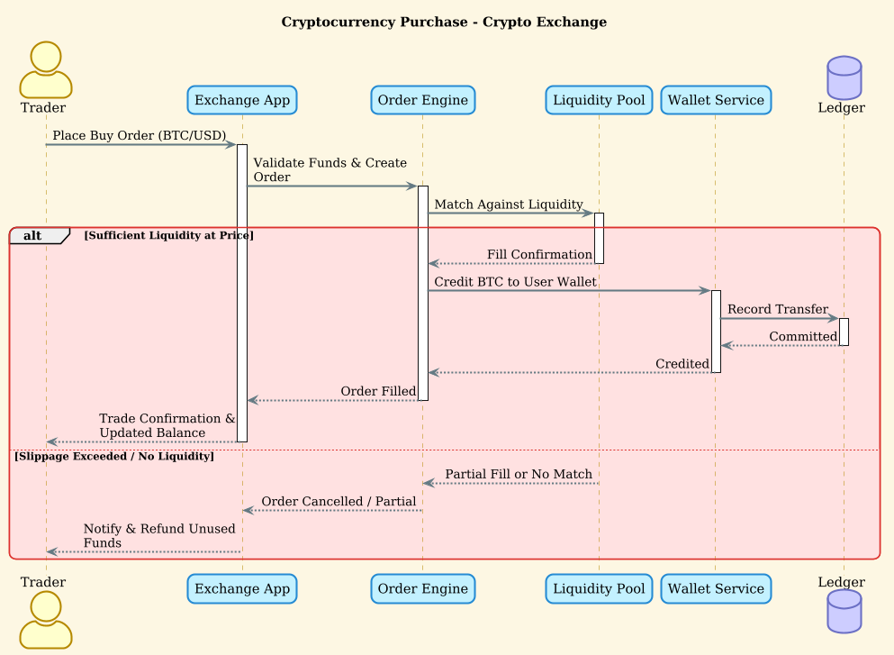
Copy the complete source code below to start editing immediately.
@startuml
!theme sunlust

title Cryptocurrency Purchase - Crypto Exchange

actor Trader
participant "Exchange App" as App
participant "Order Engine" as Engine
participant "Liquidity Pool" as LP
participant "Wallet Service" as Wallet
database "Ledger" as Ledger

Trader -> App ++ : Place Buy Order (BTC/USD)
App -> Engine ++ : Validate Funds & Create Order
Engine -> LP ++ : Match Against Liquidity
alt Sufficient Liquidity at Price
    LP --> Engine -- : Fill Confirmation
    Engine -> Wallet ++ : Credit BTC to User Wallet
    Wallet -> Ledger ++ : Record Transfer
    Ledger --> Wallet -- : Committed
    Wallet --> Engine -- : Credited
    Engine --> App -- : Order Filled
    App --> Trader -- : Trade Confirmation & Updated Balance
else Slippage Exceeded / No Liquidity
    LP --> Engine -- : Partial Fill or No Match
    Engine --> App -- : Order Cancelled / Partial
    App --> Trader -- : Notify & Refund Unused Funds
end

@endumlStep-by-Step Architectural Walkthrough
Now, let’s break down the construction of this diagram into four logical phases. This approach ensures your code remains modular and readable.
Phase 1: Canvas Configuration & Layout Directives
Every PlantUML diagram begins with configuration directives that define the visual style and overall title. We start by setting the theme to sunlust, which provides a vibrant, modern look suitable for fintech documentation.
@startuml
!theme sunlust

title Cryptocurrency Purchase - Crypto Exchange
The @startuml directive marks the beginning of the diagram, while !theme sunlust injects the CSS styling. The title directive ensures the diagram has a descriptive header for documentation purposes.
Phase 2: Declaring Core Entities, Actors, and Boundaries
Next, we define the participants. In a sequence diagram, we distinguish between external actors and internal system components.
actor Trader
participant "Exchange App" as App
participant "Order Engine" as Engine
participant "Liquidity Pool" as LP
participant "Wallet Service" as Wallet
database "Ledger" as Ledger- actor Trader: Represents the external human user initiating the trade.
- participant: Represents software components. We use aliases (e.g.,
as App) to keep the diagram clean. - database Ledger: Explicitly declares a database component, which renders a cylinder shape to distinguish persistent storage from application logic.
Phase 3: Mapping Data Flows & Key Interactions
We now map the primary success path using solid arrows for synchronous requests and dashed arrows for responses.
Trader -> App ++ : Place Buy Order (BTC/USD)
App -> Engine ++ : Validate Funds & Create Order
Engine -> LP ++ : Match Against Liquidity
The -> operator creates a solid arrow for a request. The ++ modifier indicates that the arrow is thick and bold, often used to highlight critical financial transactions. The text after the colon describes the message payload.
Phase 4: Grouping, Annotations & Visual Polish
Financial systems must handle exceptions. We use the alt block to create a combined fragment that represents alternative flows based on a condition.
alt Sufficient Liquidity at Price
    LP --> Engine -- : Fill Confirmation
    Engine -> Wallet ++ : Credit BTC to User Wallet
else Slippage Exceeded / No Liquidity
    LP --> Engine -- : Partial Fill or No Match
    Engine --> App -- : Order Cancelled / Partial
end
The alt keyword starts the conditional block. The text following alt is the condition for the first branch. The else keyword defines the fallback scenario. The end keyword closes the block. This structure ensures that the diagram clearly shows both the happy path and the error handling logic.
Syntax & Keyword Deep Dive
To master this diagram type, you must understand the core PlantUML syntax used in this finance scenario.
->(Synchronous Request): Represents a blocking call where the sender waits for a response. Used for the initial order placement and fund validation.-->(Asynchronous Response): Represents a return message. Used for confirmations and database commits.alt ... else ... end(Combined Fragment): Defines alternative execution paths. Essential for modeling trade failures, partial fills, or liquidity shortages.participant ... as ...(Alias): Allows you to assign a short nickname (e.g.,LP) to a long name (e.g.,Liquidity Pool) for cleaner diagram rendering.++(Arrow Modifier): Makes the message arrow thicker, visually emphasizing critical data transfers in the financial flow.
Best Practices & Pitfalls to Avoid
When modeling complex financial workflows, clarity is your most valuable asset. Follow these guidelines to maintain high-quality diagrams.
- Keep Message Labels Concise: Avoid pasting entire API JSON payloads into the diagram. Use high-level descriptions like
Validate Fundsinstead ofPOST /api/v1/validate {"amount": 100}. - Group Related Logic: Always use
altoroptblocks to clearly separate success paths from failure paths. This prevents the diagram from becoming a tangled web of lines. - Use Consistent Naming: Stick to the aliasing pattern (e.g.,
App,Engine) throughout the diagram to avoid confusion when referencing components in later phases. - Validate with VPasCode: Use the live preview in VPasCode to catch syntax errors immediately. The instant rendering allows you to test how the
sunlusttheme handles long participant names and adjust spacing dynamically.
Start Building PlantUML Diagrams Faster with VPasCode
Test, preview, and customize your cryptocurrency sequence diagrams instantly in the browser with VPasCode’s free PlantUML editor—no local installation required.