


In the fast-paced world of fintech and cross-border finance, clarity is currency. When designing systems like a Currency Converter and Remittance Platform, stakeholders must agree on functional boundaries before a single line of backend code is written. Ambiguity in requirements often leads to costly rework, especially when compliance and security regulations like KYC (Know Your Customer) and AML (Anti-Money Laundering) are involved.

Visual modeling bridges this gap. By creating a Use Case Diagram, architects can map out who interacts with the system (Actors) and what the system does (Use Cases) without getting bogged down in implementation details. This visual abstraction is critical for aligning business goals with technical execution.
VPasCode, the free web-based diagram-as-code editor by Visual Paradigm, empowers software engineers and architects to draft these models instantly. By using PlantUML, you can define complex financial relationships textually, preview them live in the browser, and iterate rapidly. This tutorial demonstrates how to build a professional Use Case Diagram for a Currency Converter & Remittance System, ensuring your documentation is as robust as the system you are designing.
Understanding the Model: Purpose, Scope & Problem Framing
Before diving into the syntax, it is essential to understand the abstraction we are modeling. A Use Case Diagram is a behavioral view that describes the interaction between users (or external systems) and the core functionality of the software.
Diagram Abstraction & Representation
In this specific context, the diagram models the functional requirements of a financial transaction platform.
- Actors: Represent the external entities interacting with the system. In finance, these could be human users (Senders, Receivers) or automated services (Payment Gateways, Compliance Engines).
- Use Cases: Represent the specific functional goals or services the system provides, such as “Convert Currency” or “Verify Identity”.
- System Boundary: The rectangle encapsulates the scope of the application, distinguishing internal logic from external dependencies.
Target Domain Scope & Scenario
This model focuses on the end-to-end flow of a cross-border remittance. It explicitly excludes the internal database schema or network topology, focusing purely on what the system does. The scope includes the user journey from initiating a transfer to the system’s internal compliance checks and external payment processing.
Key Takeaways & Educational Insights
By building this model, you will gain insights into:
- Boundary Definition: Clearly separating the core remittance system from external gateways.
- Dependency Management: Using include relationships to show mandatory sub-processes (e.g., sending money requires identity verification).
- Role Segregation: Distinguishing between the actions a Sender can take versus an Administrator.
Complete Diagram & Full Source Code
Below is the finalized blueprint for the Currency Converter & Remittance System. You can view the rendered result immediately by pasting this code into the VPasCode editor.
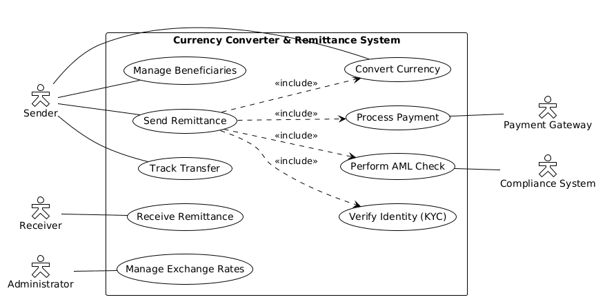
@startuml
!theme plain
left to right direction

skinparam actorStyle hollow

actor "Sender" as Sender
actor "Receiver" as Receiver
actor "Administrator" as Admin
actor "Payment Gateway" as Gateway
actor "Compliance System" as Compliance

rectangle "Currency Converter & Remittance System" {
    usecase "Convert Currency" as UC1
    usecase "Send Remittance" as UC2
    usecase "Track Transfer" as UC3
    usecase "Manage Beneficiaries" as UC4
    usecase "Receive Remittance" as UC5
    usecase "Verify Identity (KYC)" as UC6
    usecase "Manage Exchange Rates" as UC7
    usecase "Process Payment" as UC8
    usecase "Perform AML Check" as UC9
}

Sender -- UC1
Sender -- UC2
Sender -- UC3
Sender -- UC4

Receiver -- UC5

Admin -- UC7

UC2 ..> UC1 : <<include>>
UC2 ..> UC6 : <<include>>
UC2 ..> UC8 : <<include>>
UC2 ..> UC9 : <<include>>

UC8 -- Gateway
UC9 -- Compliance
@endumlStep-by-Step Architectural Walkthrough
Building this diagram is a modular process. We will construct it in four logical phases to ensure maintainability and clarity.
Phase 1: Canvas Configuration & Layout Directives
Every PlantUML diagram starts with configuration. We set the theme to ensure a clean, professional look suitable for financial documentation.
First, we initialize the diagram and apply the theme:
@startuml
!theme plain
Next, we define the layout direction. For use case diagrams, a horizontal flow often reads better for left-to-right languages, but vertical is also common. Here, we choose a left-to-right flow for the overall structure.
left to right directionWe also customize the actor appearance to match the “plain” aesthetic, ensuring they look distinct but not overly decorative.
skinparam actorStyle hollowPhase 2: Declaring Core Entities, Actors, and Boundaries
Now we define the participants. In finance, external dependencies are just as important as human users. We declare the actors representing the system’s ecosystem.
actor "Sender" as Sender
actor "Receiver" as Receiver
actor "Administrator" as Admin
actor "Payment Gateway" as Gateway
actor "Compliance System" as Compliance
Next, we define the system boundary using a rectangle. This creates the visual container for all internal use cases, clearly separating them from external actors.
rectangle "Currency Converter & Remittance System" {
    // Use cases go here
}
Phase 3: Mapping Data Flows & Key Interactions
Inside the boundary, we list the functional goals. We assign aliases (like UC1, UC2) to keep the relationship lines clean and readable.
usecase "Convert Currency" as UC1
usecase "Send Remittance" as UC2
usecase "Track Transfer" as UC3
usecase "Manage Beneficiaries" as UC4
usecase "Receive Remittance" as UC5
usecase "Verify Identity (KYC)" as UC6
usecase "Manage Exchange Rates" as UC7
usecase "Process Payment" as UC8
usecase "Perform AML Check" as UC9
Once defined, we connect the actors to their respective use cases using solid lines (--). This represents a standard association.
Sender -- UC1
Sender -- UC2
Sender -- UC3
Sender -- UC4

Receiver -- UC5
Admin -- UC7
Phase 4: Grouping, Annotations & Visual Polish
Complex workflows often involve mandatory sub-processes. For example, you cannot “Send Remittance” without “Converting Currency” or “Verifying Identity”. We use the include relationship (..>) to denote this dependency.
UC2 ..> UC1 : <>
UC2 ..> UC6 : < >
UC2 ..> UC8 : < >
UC2 ..> UC9 : < > Finally, we link internal use cases to external actors (like the Payment Gateway) to show system integrations.
UC8 -- Gateway
UC9 -- Compliance
Syntax & Keyword Deep Dive
Understanding the specific PlantUML keywords used in this model is crucial for extending it later. Here is a breakdown of the key syntax elements:
actor: Defines an external entity interacting with the system. Can be human (User) or system (API).rectangle: Creates a boundary box to group related use cases, defining the system scope.usecase: Defines a specific functional goal or service provided by the system.--: Creates a solid association line between two elements (Actor to Use Case)...>: Creates a dashed line with an arrowhead, often used for dependencies or includes.<: An annotation indicating that one use case includes the functionality of another (mandatory dependency).> skinparam: Used to customize the visual style of elements globally.
Best Practices & Pitfalls to Avoid
To maintain a high-quality diagram-as-code workflow in VPasCode, follow these architectural guidelines:
- Keep Boundaries Tight: Do not clutter the system rectangle with external actors. Keep actors outside and use cases inside. Only link actors to use cases they directly interact with.
- Meaningful Naming: Avoid generic names like “Action 1”. Use verb-noun pairs like “Verify Identity” or “Process Payment” to make the diagram self-documenting.
- Manage Complexity: If a diagram becomes too crowded, split it. One diagram for “Sender Flow” and another for “Admin Flow” might be clearer than one massive map.
- Consistent Styling: Use
skinparamdirectives early to ensure the diagram looks professional immediately, rather than tweaking individual elements.
Start Building Financial Use Case Diagrams Faster with VPasCode
Define complex financial workflows instantly with zero local installation. Test your PlantUML syntax, preview diagrams live in the browser, and share your architecture documentation online for free.