


In the fast-paced world of financial technology, clarity in system requirements is paramount. For a Debt Collection System, the complexity lies not just in processing payments, but in managing sensitive debtor data, ensuring compliance with credit regulations, and coordinating with external financial gateways. Visual modeling serves as the bridge between business stakeholders and engineering teams, translating abstract financial workflows into concrete system interactions.

Using a Use Case Diagram within VPasCode allows architects to define the functional boundaries of the system without getting bogged down in implementation details. This diagram-as-code approach enhances architectural clarity, enables rapid visual prototyping, and ensures that living technical documentation remains synchronized with the codebase. By leveraging PlantUML in the VPasCode web editor, teams can instantly render and validate these models, ensuring that every actor—from the debt collector to the credit bureau—has a clearly defined role in the ecosystem.
Understanding the Model: Purpose, Scope & Problem Framing
Before diving into the syntax, it is essential to ground the reader in the fundamental modeling abstraction and domain scenario. This specific diagram type models the functional requirements of the system from the perspective of external entities.
Diagram Abstraction & Representation
A Use Case Diagram is the ideal visual tool for this problem because it focuses on what the system does rather than how it does it. In the context of a Debt Collection System:
- Actors represent user roles (e.g., Collector, Administrator) or external systems (e.g., Payment Gateway) that interact with the software.
- Use Cases represent high-level functional goals, such as “Log Payments” or “Verify Credit History,” which are the value propositions of the system.
- Relationships (associations and includes) map the flow of information and dependencies between actors and functions.
Target Domain Scope & Scenario
The system boundary, encapsulated within the rectangle labeled “Debt Collection System,” defines the scope of the application. Internally, the system manages debtor accounts and financial reporting. Externally, it relies on third-party services to validate credit history and process payments. This separation is critical for finance applications where data sovereignty and API integrations are strictly regulated.
Key Takeaways & Educational Insights
By constructing this model, you will gain architectural insights into boundary clarity and operational understanding. You will learn how to distinguish between internal administrative tasks (like managing users) and core business operations (like processing payments), ensuring that the system architecture supports the specific compliance and workflow needs of the finance industry.
Complete Diagram & Full Source Code
Below is the finished blueprint for the Debt Collection System. This diagram utilizes the sunlust theme for a professional, modern aesthetic and clearly delineates the interactions between internal staff and external financial services.
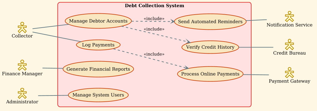
Copy the complete source code below into the VPasCode editor to render and customize your own version instantly.
@startuml
!theme sunlust
left to right direction

skinparam actorStyle hollow

actor "Collector" as collector
actor "Finance Manager" as manager
actor "Administrator" as admin

rectangle "Debt Collection System" {
    usecase "Manage Debtor Accounts" as uc1
    usecase "Log Payments" as uc2
    usecase "Generate Financial Reports" as uc3
    usecase "Manage System Users" as uc4
    usecase "Process Online Payments" as uc5
    usecase "Verify Credit History" as uc6
    usecase "Send Automated Reminders" as uc7
}

actor "Payment Gateway" as payment_gateway
actor "Credit Bureau" as credit_bureau
actor "Notification Service" as notification_service

collector -- uc1
collector -- uc2
manager -- uc3
admin -- uc4

uc5 -- payment_gateway
uc6 -- credit_bureau
uc7 -- notification_service

uc2 ..> uc5 : <<include>>
uc1 ..> uc6 : <<include>>
uc1 ..> uc7 : <<include>>
@endumlStep-by-Step Architectural Walkthrough
Follow these phases to construct this diagram from scratch, understanding the architectural intent behind every line of code.
Phase 1: Canvas Configuration & Layout Directives
Every PlantUML diagram begins with setup directives that control the visual style and orientation. In this finance scenario, we want a clean, horizontal flow to match the natural reading direction of business processes.
We start by setting the theme to sunlust, which provides a vibrant, modern color palette suitable for professional documentation. We also enforce a left-to-right direction to ensure the system boundary and actors align logically.
!theme sunlust
left to right direction
Phase 2: Declaring Core Entities, Actors, and Boundaries
Next, we define the participants. In VPasCode, actors are defined using the actor keyword. We assign unique IDs (like collector) to reference them later in relationships.
The system boundary is crucial for defining scope. We use a rectangle to enclose the internal use cases, visually separating what the system controls from external dependencies.
skinparam actorStyle hollow

actor "Collector" as collector
actor "Finance Manager" as manager
actor "Administrator" as admin

rectangle "Debt Collection System" {
    usecase "Manage Debtor Accounts" as uc1
    ...
}
Phase 3: Mapping Data Flows & Key Interactions
Now we connect the actors to their responsibilities. Solid lines (--) represent direct associations. For example, the collector is directly associated with managing debtor accounts and logging payments.
We also introduce external system actors, such as the Payer Gateway and Credit Bureau. These represent third-party integrations that the system must communicate with to function correctly.
collector -- uc1
collector -- uc2
manager -- uc3
admin -- uc4
Phase 4: Grouping, Annotations & Visual Polish
Finally, we define complex dependencies using the include relationship. This indicates that one use case is a mandatory part of another. For instance, Manage Debtor Accounts includes Verify Credit History.
We use dotted arrows (..>) with the «include» stereotype to show this dependency clearly, ensuring the diagram communicates that credit verification is a prerequisite for account management.
uc1 ..> uc6 : <>
uc1 ..> uc7 : < > Syntax & Keyword Deep Dive
To master PlantUML within VPasCode, it is vital to understand the specific keywords and arrow conventions used in this diagram.
actor: Defines a participant (human or system) interacting with the system. Theskinparam actorStyle hollowdirective customizes the visual appearance of these icons.usecase: Represents a functional unit or goal within the system boundary. Each use case is given a unique ID (e.g.,uc1) for referencing.rectangle: Creates a container to group use cases, defining the system boundary and separating internal logic from external actors.--(Solid Line): Indicates a direct association or communication path between an actor and a use case...>(Dotted Line): Used for dependencies. When combined with<<include>>, it signifies that the source use case incorporates the functionality of the target use case.!theme: A directive that applies a specific visual style preset to the entire diagram, ensuring consistency and professional aesthetics.
Best Practices & Pitfalls to Avoid
When modeling finance workflows, precision is key. Follow these best practices to maintain high-quality diagrams:
- Keep Boundaries Clear: Always use a
rectangleto define the system scope. Avoid placing external actors (like the Credit Bureau) inside the boundary, as this confuses the system’s internal logic with external dependencies. - Use Descriptive Names: Avoid generic names like “Action 1.” Instead, use verbs and nouns like “Log Payments” or “Generate Financial Reports” to make the diagram self-documenting.
- Manage Visual Complexity: If the diagram becomes too crowded, consider splitting it into multiple diagrams (e.g., one for Admin functions, one for Collector functions) or using packages to group related use cases.
- Leverage Includes for Reusability: Use
<<include>>to highlight mandatory sub-processes. This helps stakeholders understand that certain steps, like Credit Verification, are non-negotiable parts of the workflow.
Try It Yourself with VPasCode
Start Building PlantUML Use Case Diagrams Faster with VPasCode
Experience instant live browser preview, zero local installation, and interactive syntax testing to prototype your finance workflows online today.