


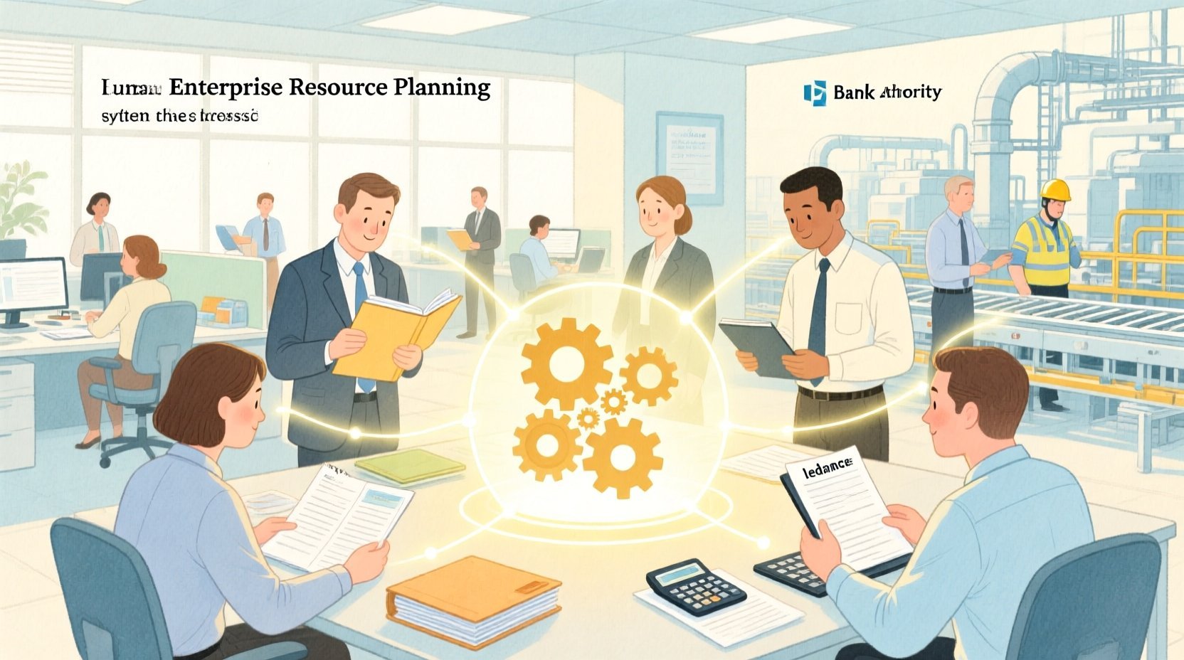
In the complex landscape of manufacturing and enterprise operations, clarity is currency. An Enterprise Resource Planning (ERP) system serves as the central nervous system of an organization, integrating critical functions like human resources, finance, inventory, and production. However, the sheer complexity of these systems often leads to ambiguity in requirements and stakeholder expectations. This is where visual modeling becomes indispensable.
Use Case diagrams provide a high-level view of system functionality, mapping the interactions between actors (users or external systems) and the system itself. By using PlantUML within the VPasCode editor, architects and developers can rapidly prototype, document, and validate these interactions without the overhead of traditional drag-and-drop tools. This approach ensures that technical documentation remains a living artifact, synchronized with the codebase and accessible to all stakeholders.
Understanding the Model: Purpose, Scope & Problem Framing
Before diving into the syntax, it is crucial to understand the architectural abstraction we are building. A Use Case diagram is not a flowchart; it is a contract of functionality.
Diagram Abstraction & Representation
This model defines the “what” of the system, not the “how”. It identifies the active entities (actors) that require services from the ERP system and the specific goals (use cases) they aim to achieve. In this context, primary actors are internal users who initiate actions, while secondary actors represent external dependencies such as banks or tax authorities that receive or provide data.
Target Domain Scope & Scenario
The scope of this diagram is strictly limited to the core operational backbone of an ERP system. It covers the seven most critical use cases: Employee Management, Payroll, Financial Reporting, Inventory, Procurement, Sales, and Production Planning. We intentionally exclude lower-level implementation details to maintain a strategic overview that is understandable by both business stakeholders and technical teams.
Key Takeaways & Educational Insights
By constructing this diagram, you will gain clarity on system boundaries, identify potential integration points with external entities (like the Bank or Tax Authority), and ensure that all critical user roles have defined interaction paths. This visual clarity reduces the risk of scope creep and miscommunication during the development lifecycle.
Complete Diagram & Full Source Code
Below is the complete blueprint for the Enterprise Resource Planning Use Case Diagram. You can view the rendered result immediately or use the interactive editor to experiment with modifications.
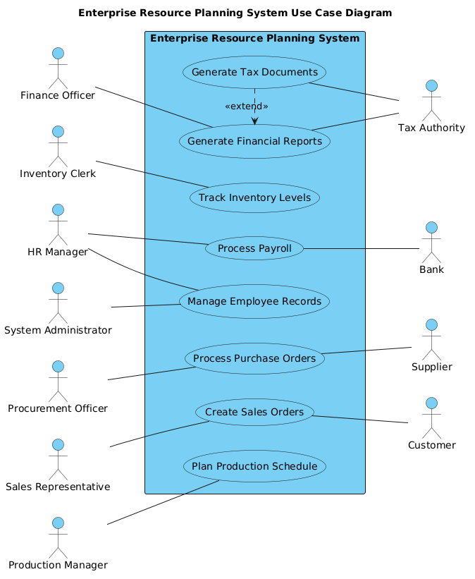
@startuml
!include https://static.visual-paradigm.com/web/resources/plantuml-stdlib/themes/vp.puml

title Enterprise Resource Planning System Use Case Diagram

/'
This diagram illustrates the core functionalities of an Enterprise Resource
Planning (ERP) system and its interactions with various stakeholders. The ERP
system integrates essential business processes including human resources, finance,
inventory management, procurement, sales, production planning, and system
administration. Primary actors represent internal users who directly interact with
the system to perform daily operations, while secondary actors represent external
entities that receive information from or provide data to the system. The diagram
focuses on the seven most critical use cases that form the backbone of enterprise
operations. An extend relationship shows optional tax document generation that
extends financial reporting under specific regulatory conditions.
'/

left to right direction

actor "HR Manager" as HRManager
actor "Finance Officer" as FinanceOfficer
actor "Inventory Clerk" as InventoryClerk
actor "Procurement Officer" as ProcurementOfficer
actor "Sales Representative" as SalesRep
actor "Production Manager" as ProductionManager
actor "System Administrator" as SysAdmin

rectangle "Enterprise Resource Planning System" {
    usecase "Manage Employee Records" as ManageEmployee
    usecase "Process Payroll" as ProcessPayroll
    usecase "Generate Financial Reports" as GenerateFinReport
    usecase "Track Inventory Levels" as TrackInventory
    usecase "Process Purchase Orders" as ProcessPO
    usecase "Create Sales Orders" as CreateSalesOrder
    usecase "Plan Production Schedule" as PlanProduction
    usecase "Generate Tax Documents" as GenerateTaxDoc
}

actor "Bank" as Bank
actor "Tax Authority" as TaxAuthority
actor "Supplier" as Supplier
actor "Customer" as Customer

' Primary actors on the left
HRManager -- ManageEmployee
HRManager -- ProcessPayroll

FinanceOfficer -- GenerateFinReport

InventoryClerk -- TrackInventory

ProcurementOfficer -- ProcessPO

SalesRep -- CreateSalesOrder

ProductionManager -- PlanProduction

SysAdmin -- ManageEmployee

' Secondary actors on the right
ProcessPayroll -- Bank
GenerateFinReport -- TaxAuthority
ProcessPO -- Supplier
CreateSalesOrder -- Customer
GenerateTaxDoc -- TaxAuthority

' Extend relationship
GenerateTaxDoc .> GenerateFinReport : <<extend>>

@endumlStep-by-Step Architectural Walkthrough
Building a professional diagram in VPasCode is a structured process. We will break down the construction of this ERP model into four distinct phases.
Phase 1: Canvas Configuration & Layout Directives
Every PlantUML diagram begins with setup. We start by including the VP theme to ensure consistent styling that matches the VPasCode ecosystem. We also define the title and a comment block to explain the diagram’s context. Finally, we set the layout direction to left to right, which is ideal for Use Case diagrams where primary actors are typically on the left.
@startuml
!include https://static.visual-paradigm.com/web/resources/plantuml-stdlib/themes/vp.puml

title Enterprise Resource Planning System Use Case Diagram

/'
This diagram illustrates the core functionalities...
'/

left to right direction
Phase 2: Declaring Core Entities, Actors, and Boundaries
Next, we define the actors. In PlantUML, actors are declared using the actor keyword followed by a label and an alias. We separate primary actors (internal users) from secondary actors (external systems). The primary actors are listed first, followed by the system boundary.
actor "HR Manager" as HRManager
actor "Finance Officer" as FinanceOfficer

rectangle "Enterprise Resource Planning System" {
    usecase "Manage Employee Records" as ManageEmployee
    usecase "Process Payroll" as ProcessPayroll
}
Phase 3: Mapping Data Flows & Key Interactions
With the actors and use cases defined, we establish their relationships. For Use Case diagrams, associations are drawn using the -- operator. We place primary actors on the left connecting to use cases, and secondary actors on the right. This visual distinction helps stakeholders quickly identify who initiates actions versus who receives data.
HRManager -- ManageEmployee
ProcessPayroll -- Bank
Phase 4: Grouping, Annotations & Visual Polish
Finally, we handle complex relationships like the extend relationship. In this ERP model, generating tax documents is an optional extension of financial reporting. We use the .> operator with the <<extend>> stereotype to denote this dependency. This phase ensures the diagram is not just a list of features, but a representation of logical dependencies.
GenerateTaxDoc .> GenerateFinReport : <Syntax & Keyword Deep Dive
To master diagramming in PlantUML, you must understand the specific keywords and conventions used. Here is a breakdown of the essential syntax elements in this ERP model:
actor: Defines an entity that interacts with the system. Can be human (e.g.,HR Manager) or external (e.g.,Bank).usecase: Defines a specific function or goal within the system boundary.rectangle: Creates the system boundary (the "black box"), grouping all internal use cases.--: Represents an association or communication link between an actor and a use case..>: Represents a directed relationship, often used for dependency or extension logic.<<extend>>: A stereotype indicating that one use case adds functionality to another under specific conditions.
Best Practices & Pitfalls to Avoid
When creating diagrams with VPasCode, adhering to best practices ensures your documentation remains useful over time.
- Keep Boundaries Clear: Ensure the system boundary (
rectangle) accurately reflects what is inside the ERP system versus what is external. - Avoid Over-Clustering: If a diagram becomes too crowded, consider splitting it into sub-diagrams or focusing on specific modules (e.g., HR vs. Finance).
- Consistent Naming: Use verb-noun phrases for use cases (e.g., "Process Payroll" instead of just "Payroll") to emphasize action.
- Separate Primary and Secondary: Visually distinguish between internal users and external systems to clarify data flow direction.
Start Building ERP Use Case Diagrams Faster with VPasCode
Instantly prototype your Enterprise Resource Planning system interactions with a free, browser-based PlantUML editor that requires zero local installation.