


In the fast-paced world of online entertainment, the reliability and clarity of system architecture are paramount. A Gaming Matchmaking Server System is the backbone of multiplayer experiences, responsible for pairing players fairly and efficiently. However, defining the scope of this system can be challenging. How do we distinguish between what the system does versus what external services handle? This is where visual modeling becomes critical.
Using a Use Case Diagram provides a high-level view of the system’s functionality from the perspective of its users and external interfaces. By leveraging VPasCode, a free web-based diagram-as-code tool, architects can rapidly prototype these diagrams. VPasCode allows you to write PlantUML code and see instant, live rendering in the browser, eliminating the need for local Java installations or complex environment setups. This tutorial demonstrates how to structure a professional Use Case diagram that clearly delineates the boundaries of a Matchmaking Server, ensuring all stakeholders understand the system’s capabilities.
Understanding the Model: Purpose, Scope & Problem Framing
Diagram Abstraction & Representation
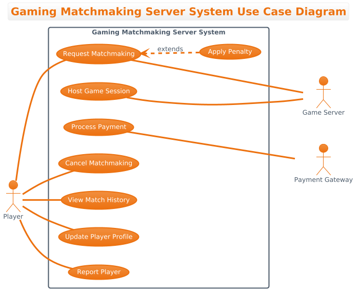
A Use Case Diagram is not a flowchart; it is a functional blueprint. It models the what of a system rather than the how. In this context, the diagram abstracts the complex backend logic of the Matchmaking Server into discrete functional goals (Use Cases) and the entities interacting with them (Actors).
- Actors: Represent roles that interact with the system. In this diagram, the Player is the primary actor initiating actions, while Game Server and Payment Gateway act as secondary actors supporting the system’s operations.
- Use Cases: Represent specific services or functions the system provides, such as Request Matchmaking or Process Payment.
- System Boundary: The rectangle encloses the functionality owned by the Matchmaking Server System itself, separating internal logic from external dependencies.
Target Domain Scope & Scenario
This diagram focuses specifically on the Gaming Matchmaking Server System. It intentionally excludes the internal code logic of the game client or the specific implementation details of the payment processor. The scope is defined by the interactions that cross the system boundary. It covers the lifecycle of a match request, from initiation by the player to the hosting of the session by the Game Server, and includes administrative functions like penalties and reporting.
Key Takeaways & Educational Insights
By constructing this diagram, you will gain clarity on system ownership. You will learn how to distinguish between primary interactions (Player vs. System) and secondary dependencies (System vs. External Services). This separation is vital for microservices architecture, ensuring that the Matchmaking Service remains focused on pairing logic without being cluttered by unrelated concerns.
Complete Diagram & Full Source Code
Below is the finished blueprint of the Gaming Matchmaking Server System Use Case Diagram. You can view the rendered output immediately using the VPasCode editor.
Copy the complete source code below to replicate this diagram. This code is optimized for the VPasCode editor.
@startuml
!theme aws-orange

title Gaming Matchmaking Server System Use Case Diagram
/'
This diagram illustrates the use cases for a Gaming Matchmaking Server System.
The system facilitates online multiplayer game sessions by matching players
based on skill level, region, and preferences. Primary actors include Players
who initiate matchmaking requests and manage their profiles, while secondary
actors include Game Servers that host the actual game sessions and Payment
Gateways that handle subscription or premium feature transactions. The system
ensures fair and efficient pairing to enhance user experience.
'/

left to right direction

actor Player
actor "Game Server" as GameServer
actor "Payment Gateway" as PaymentGateway

rectangle "Gaming Matchmaking Server System" {
    usecase "Request Matchmaking" as RequestMatchmaking
    usecase "Cancel Matchmaking" as CancelMatchmaking
    usecase "View Match History" as ViewMatchHistory
    usecase "Update Player Profile" as UpdateProfile
    usecase "Process Payment" as ProcessPayment
    usecase "Host Game Session" as HostGameSession
    usecase "Report Player" as ReportPlayer
    usecase "Apply Penalty" as ApplyPenalty
}

Player -- RequestMatchmaking
Player -- CancelMatchmaking
Player -- ViewMatchHistory
Player -- UpdateProfile
Player -- ReportPlayer

RequestMatchmaking <.. ApplyPenalty : extends

RequestMatchmaking --- GameServer
HostGameSession --- GameServer
ProcessPayment --- PaymentGateway

@endumlStep-by-Step Architectural Walkthrough
Phase 1: Canvas Configuration & Layout Directives
Every PlantUML diagram begins with setup directives that define the visual theme and layout. In this diagram, we prioritize readability and brand alignment using the aws-orange theme. We also define the diagram title and a descriptive comment block to provide immediate context for anyone reviewing the code.
!theme aws-orange

title Gaming Matchmaking Server System Use Case Diagram
/'
This diagram illustrates the use cases for a Gaming Matchmaking Server System...
'/

left to right direction
The left to right direction directive ensures the diagram flows logically from left to right, which is standard for actor-based diagrams where primary actors are positioned on the left.
Phase 2: Declaring Core Entities, Actors, and Boundaries
Next, we declare the actors. We distinguish between the Player (the human user) and the secondary actors like Game Server and Payment Gateway. We then define the system boundary using a rectangle, which visually contains all the use cases belonging to this specific service.
actor Player
actor "Game Server" as GameServer
actor "Payment Gateway" as PaymentGateway

rectangle "Gaming Matchmaking Server System" {
    usecase "Request Matchmaking" as RequestMatchmaking
    usecase "Cancel Matchmaking" as CancelMatchmaking
    ...
}
Using as aliases (e.g., as GameServer) allows us to reference complex actor names with shorter identifiers in relationship lines later in the code.
Phase 3: Mapping Data Flows & Key Interactions
Now we connect the actors to the use cases. The syntax -- creates a solid association line without arrowheads, which is the standard for Use Case diagrams to denote a relationship. We map the Player to their core actions like Request Matchmaking and Update Profile. We also connect secondary actors to the specific use cases they support, such as the Game Server supporting the Host Game Session use case.
Player -- RequestMatchmaking
Player -- CancelMatchmaking

RequestMatchmaking --- GameServer
HostGameSession --- GameServer
Note that --- is used for secondary associations to visually differentiate them from primary user interactions, though both represent solid lines.
Phase 4: Grouping, Annotations & Visual Polish
Finally, we handle advanced relationships like extends. In this scenario, Apply Penalty is an extension of Request Matchmaking. This implies that under certain conditions (like a violation during the request phase), the penalty logic is triggered. We use the <.. syntax to denote the extension relationship.
RequestMatchmaking <.. ApplyPenalty : extendsThis completes the diagram, ensuring all actors, boundaries, and interactions are clearly defined within the VPasCode editor.
Syntax & Keyword Deep Dive
Understanding the specific PlantUML syntax allows you to modify and extend this diagram easily. Here are the key keywords used in this model:
!theme: Sets the visual color scheme for the entire diagram. We usedaws-orangeto match a specific branding style./'...'/: Defines a comment block. This text appears in the diagram description but is not rendered as a graphical element, perfect for architectural context.actor: Declares an external entity interacting with the system. Can be a human (Player) or another system (Game Server).rectangle: Creates a system boundary. Everything inside this block belongs to the specific system being modeled.usecase: Defines a specific function or service provided by the system.--: Creates a solid association line between an actor and a use case without an arrowhead.<.. extends: Defines an extension relationship. The extending use case adds behavior to the base use case under specific conditions.
Best Practices & Pitfalls to Avoid
When building diagrams with VPasCode, follow these guidelines to maintain clarity:
- Maintain Clear Boundaries: Ensure every use case inside the
rectangleis a responsibility of the system itself. Do not include external processes like "Payment Gateway Processing" inside the Matchmaking boundary; instead, link the use case to the external actor. - Consistent Naming: Use verb-noun phrases for use cases (e.g., Request Matchmaking) rather than nouns. This clarifies the action being performed.
- Avoid Over-Complexity: If a diagram becomes too crowded, split it into sub-systems. This diagram keeps the scope tight to the Matchmaking Server to avoid confusion with the broader game architecture.
- Use Aliases for Readability: When actor names are long (e.g.,
"Payment Gateway"), useasaliases (e.g.,PaymentGateway) in relationship lines to keep the code clean.
Start Building Use Case Diagrams Faster with VPasCode
Define your system boundaries and actor interactions instantly with VPasCode. No installation required—just write code and preview your diagram in the browser.