


In the high-stakes world of modern manufacturing, the gap between physical machinery and digital control systems is bridged by robust software architecture. Industrial Automation Systems are the backbone of smart factories, orchestrating everything from robotic assembly arms to temperature sensors and safety interlocks. However, documenting these complex interactions using static images is often a maintenance nightmare. As systems evolve, diagrams become outdated, leading to architectural drift.
This is where diagram-as-code transforms the workflow. By modeling your Industrial Automation System using PlantUML within VPasCode, you create living documentation that stays in sync with your design. This approach allows software architects and manufacturing engineers to rapidly prototype system hierarchies, define entity relationships, and visualize the lifecycle of physical assets without the friction of manual drawing tools.
In this masterclass, we will construct a comprehensive class diagram that maps the core components of an industrial automation environment. We will cover production lines, workstations, controllers (PLCs and CNCs), and the sensor-actuator loops that drive physical processes.
Understanding the Model: Purpose, Scope & Problem Framing
Before diving into the syntax, it is crucial to understand the architectural abstraction we are building. This diagram is not merely a list of classes; it is a structural blueprint of a cyber-physical system.
Diagram Abstraction & Representation
A PlantUML Class Diagram in this context serves as the contract between the hardware and the software. It defines:
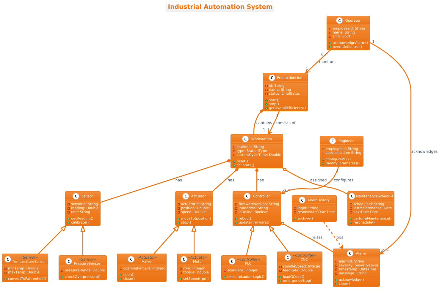
- Entity Hierarchy: How high-level assets (Production Lines) decompose into smaller units (Workstations, Controllers).
- Behavioral Interfaces: The methods available to operators and engineers (e.g.,
start(),reboot(),calibrate()). - State Management: How status data (LineStatus, SeverityLevel) flows through the system.
Target Domain Scope & Scenario
This model focuses on the control and monitoring layer of a manufacturing plant. It intentionally excludes low-level network protocols (like Modbus or OPC UA) to focus on the object-oriented representation of the system logic. The scope covers:
- Physical Assets: Machines, sensors, and actuators.
- Control Logic: PLCs and CNC controllers managing the hardware.
- Human Interaction: Operators and Engineers interacting with the system.
- Event Handling: Alarms and maintenance scheduling.
Key Takeaways & Educational Insights
By the end of this tutorial, you will gain clarity on how to represent composition vs. aggregation in industrial contexts. For instance, understanding that a Workstation contains a Controller (strong lifecycle) is different from a Controller raising an Alarm (weak lifecycle). You will also learn how to use inheritance to model specialized hardware types like PLC and CNC under a generic Controller base.
Complete Diagram & Full Source Code
Below is the finished blueprint. This diagram models a hierarchical structure of physical assets, their control logic, and the roles of different users (operators and engineers) in managing the system.
@startuml
!theme aws-orange
title Industrial Automation System

/'
This class diagram models the core components of an industrial automation system
used in a manufacturing plant. The system manages production lines, equipment,
sensors, controllers, and operator interactions. It supports real-time monitoring,
control, and alarm handling. The diagram illustrates the hierarchical structure
of physical assets, their control logic, and the roles of different users
(operators and engineers) in managing the system.
'/

class ProductionLine {
  - id: String
  - name: String
  - status: LineStatus
  + start()
  + stop()
  + getOverallEfficiency()
}

class Workstation {
  - stationId: String
  - type: StationType
  - currentCycleTime: Double
  + reset()
  + calibrate()
}

class Controller {
  - firmwareVersion: String
  - ipAddress: String
  - isOnline: Boolean
  + reboot()
  + updateFirmware()
}

class PLC <<Controller>> {
  - scanRate: Integer
  + executeLadderLogic()
}

class CNC <<Controller>> {
  - spindleSpeed: Integer
  - feedRate: Double
  + loadGCode()
  + emergencyStop()
}

class Sensor {
  - sensorId: String
  - reading: Double
  - unit: String
  + getReading()
  + calibrate()
}

class TemperatureSensor <<Sensor>> {
  - minTemp: Double
  - maxTemp: Double
  + convertToFahrenheit()
}

class PressureSensor <<Sensor>> {
  - pressureRange: Double
  + checkOverpressure()
}

class Actuator {
  - actuatorId: String
  - position: Double
  - speed: Double
  + moveTo(position)
  + stop()
}

class Motor <<Actuator>> {
  - rpm: Integer
  - torque: Double
  + setSpeed(rpm)
}

class Valve <<Actuator>> {
  - openingPercent: Integer
  + open()
  + close()
}

class Alarm {
  - alarmId: String
  - severity: SeverityLevel
  - timestamp: DateTime
  - message: String
  + acknowledge()
  + clear()
}

class AlarmHistory {
  - logId: String
  - resolvedAt: DateTime
  + archive()
}

class Operator {
  - employeeId: String
  - name: String
  - shift: Shift
  + acknowledgeAlarm()
  + overrideControl()
}

class Engineer {
  - employeeId: String
  - specialization: String
  + configurePLC()
  + modifyParameters()
}

class MaintenanceSchedule {
  - scheduleId: String
  - lastMaintenance: Date
  - nextDue: Date
  + performMaintenance()
  + reschedule()
}

' Generalization (inheritance)
Controller <|-- PLC
Controller <|-- CNC
Sensor <|-- TemperatureSensor
Sensor <|-- PressureSensor
Actuator <|-- Motor
Actuator <|-- Valve

' Composition (strong lifecycle)
ProductionLine *-- Workstation : contains
Workstation *-- Controller : has
Workstation *-- Sensor : has
Workstation *-- Actuator : has

' Aggregation (weak lifecycle)
Controller o-- Alarm : raises
Workstation o-- MaintenanceSchedule : assigned

' Association (bi-directional)
Operator "1" --> "0..*" Alarm : acknowledges
Engineer "1" --> "0..*" Controller : configures
Operator "0..*" --> "1" ProductionLine : monitors

' Dependency (dashed)
AlarmHistory ..> Alarm : logs

' Association with role
ProductionLine "1" --> "1..*" Workstation : consists of
@endumlStep-by-Step Architectural Walkthrough
Now that we have the complete code, let’s break down the construction process into four logical phases. This breakdown helps you understand how to assemble complex diagrams incrementally.
Phase 1: Canvas Configuration & Layout Directives
Every PlantUML diagram starts with configuration. We begin by setting the visual theme and defining the scope of the diagram.
First, we apply the !theme aws-orange directive. This gives the diagram a consistent, professional look suitable for industrial dashboards. Next, we define the title to ensure the diagram is self-documenting. Finally, we add a comment block using /' and '/ to provide context. This context is vital for future maintainers who need to understand the problem space without reading the code.
!theme aws-orange
title Industrial Automation System

/'
This class diagram models the core components of an industrial automation system
used in a manufacturing plant...
'/
Phase 2: Declaring Core Entities, Actors, and Boundaries
The foundation of the system lies in the core entities. We define the ProductionLine and Workstation classes first, as they represent the highest level of hierarchy. We then introduce the Controller class, which acts as the base for specific hardware types.
Notice how we define attributes (private with -) and methods (public with +). This encapsulation is critical for defining the public API of your system components.
class ProductionLine {
  - id: String
  - name: String
  - status: LineStatus
  + start()
  + stop()
  + getOverallEfficiency()
}

class Workstation {
  - stationId: String
  - type: StationType
  - currentCycleTime: Double
  + reset()
  + calibrate()
}
Phase 3: Mapping Data Flows & Key Interactions
Industrial automation relies heavily on polymorphism. Instead of creating separate classes for every sensor or controller, we use inheritance to create a hierarchy. We define a base Controller and then extend it with PLC and CNC. Similarly, we create a Sensor base and extend it to TemperatureSensor and PressureSensor.
This approach reduces redundancy. Both PLCs and CNCs share the ability to reboot() and updateFirmware(), which is defined in the base class.
' Generalization (inheritance)
Controller <|-- PLC
Controller <|-- CNC
Sensor <|-- TemperatureSensor
Sensor <|-- PressureSensor
Phase 4: Grouping, Annotations & Visual Polish
The final phase involves defining relationships. In manufacturing, the lifecycle of components matters. A Workstation cannot exist without its Controller, so we use Composition (*--). However, an Alarm can exist independently of a specific Controller instance for logging purposes, so we use Aggregation (o--).
We also define roles for human actors. An Operator monitors a ProductionLine, while an Engineer configures Controller instances. These associations clarify responsibility boundaries within the organization.
' Composition (strong lifecycle)
ProductionLine *-- Workstation : contains
Workstation *-- Controller : has

' Aggregation (weak lifecycle)
Controller o-- Alarm : raises
Workstation o-- MaintenanceSchedule : assigned
Syntax & Keyword Deep Dive
To master PlantUML class diagrams, you must understand the specific keywords used to define structure. Here is a breakdown of the syntax features utilized in this Industrial Automation System diagram:
class: Defines a class entity. It can include attributes and methods within curly braces.<<stereotype>>: Used to mark specialized classes (e.g.,<<Controller>>) to indicate they inherit from a specific base type.<|--: Represents Generalization (Inheritance). The arrow points from the child class to the parent class (e.g.,PLC <|-- Controller).*--: Represents Composition. This indicates a strong "part-of" relationship where the child cannot exist without the parent (e.g., aWorkstationowns itsController).o--: Represents Aggregation. This indicates a weak "has-a" relationship where the child can exist independently (e.g., aControllerraises anAlarmwhich might be archived elsewhere).-->: Represents Association. This indicates a standard relationship or navigation path between two classes...>: Represents Dependency. A dashed line indicating that one class depends on another (e.g.,AlarmHistorydepends onAlarmto log data)."1" --> "0..*": Multiplicity notation. Defines cardinality constraints, such as one Operator acknowledging zero or many Alarms.
Best Practices & Pitfalls to Avoid
When modeling complex industrial systems, clarity is paramount. Follow these best practices to ensure your diagrams remain maintainable:
- Respect Lifecycle Boundaries: Use Composition (
*--) only when the child's lifecycle is strictly bound to the parent. Do not use it for temporary or independent entities like Alarms or Logs. - Keep Namespaces Logical: Group related classes (like all Sensor types) visually or logically. Avoid scattering related components across the canvas to maintain readability.
- Use Stereotypes for Clarity: When using inheritance, clearly mark the base class with a stereotype or ensure the relationship is explicit. This helps developers understand which methods are inherited.
- Document the "Why": Use the comment block (/' ... '/) to explain the architectural intent, not just the code syntax. This helps future engineers understand the business logic behind the model.
Start Building Industrial Automation Diagrams Faster with VPasCode
Test, preview, and customize your PlantUML class diagrams online instantly with VPasCode—no local installation or setup required.