


Introduction: Visualizing Financial Workflows with Diagram-as-Code
In the high-stakes environment of fintech and lending systems, clarity is currency. When architects and developers design complex workflows like loan applications, ambiguity can lead to costly integration errors or compliance breaches. A loan application process involves multiple touchpoints: customer interfaces, backend services, external credit bureaus, and human underwriters. Mapping these interactions requires a precise, time-ordered view that captures both synchronous requests and asynchronous callbacks.
Traditional drag-and-drop diagramming tools often struggle with versioning and maintainability. This is where diagram-as-code transforms the development lifecycle. By using PlantUML within VPasCode, financial engineers can write text-based specifications that render instantly into professional sequence diagrams. This approach ensures that the visual documentation remains synchronized with the codebase, accessible via a free, browser-based editor without any local installation.
This masterclass guides you through building a comprehensive Loan Application Sequence Diagram. We will model the flow from initial submission to final approval, incorporating conditional logic for credit checks and document verification. By the end of this guide, you will understand how to leverage VPasCode to create living documentation that stakeholders can understand at a glance.
Understanding the Model: Purpose, Scope & Problem Framing
Before writing a single line of code, it is crucial to understand the abstraction we are building. A sequence diagram is not merely a picture; it is a behavioral contract describing how objects or participants interact over time.
Diagram Abstraction & Representation
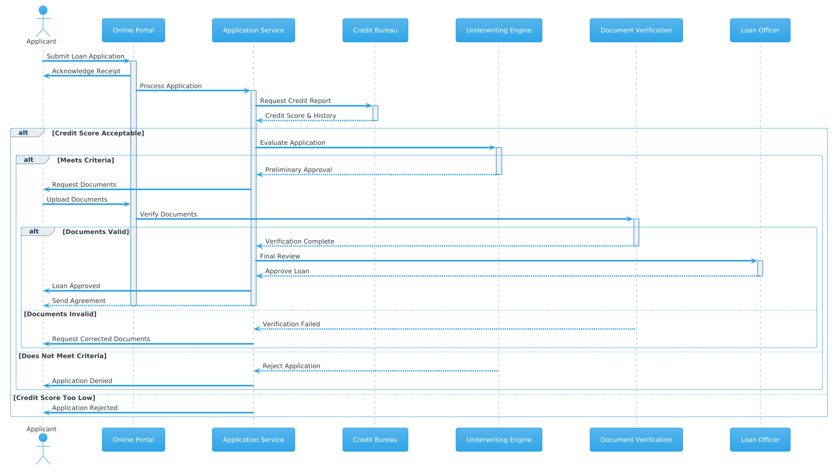
In this specific finance domain scenario, the sequence diagram serves as a runtime map of the loan origination process. We model:
- Lifelines: Representing the actors (Applicant, Loan Officer) and system components (Portal, App Service, Credit Bureau). These vertical lines represent the existence of an entity throughout the interaction timeline.
- Messages: Horizontal arrows indicating data transfer or method calls. Solid arrows denote synchronous requests, while dashed arrows represent asynchronous responses.
- Activation Bars: Rectangles on lifelines showing when an object is actively performing a task.
- Combined Fragments: Blocks like
altandelsethat represent decision points, such as whether a credit score meets the threshold.
Target Domain Scope & Scenario
The scope of this diagram covers the end-to-end lifecycle of a loan application within a digital lending platform. It intentionally excludes backend database persistence logic to focus on the service orchestration layer. The boundaries include:
- External Systems: The Credit Bureau (external dependency) and the Applicant (human actor).
- Internal Services: The Online Portal, Application Service, Underwriting Engine, and Document Verification Service.
- Human Intervention: The Loan Officer role, representing a manual review step required for final approval.
Key Takeaways & Educational Insights
By constructing this model, you will gain insights into:
- How to manage complex conditional flows using alt blocks for alternative paths.
- The importance of activation and deactivation to visualize resource locking and processing time.
- How to structure a finance-grade diagram that clearly distinguishes between automated decisions and human reviews.
Complete Diagram & Full Source Code
Below is the final blueprint for the Loan Application Sequence Diagram. This code utilizes the cerulean theme for a clean, professional aesthetic suitable for technical documentation.
@startuml
!theme cerulean

actor Applicant
participant "Online Portal" as Portal
participant "Application Service" as AppService
participant "Credit Bureau" as CreditBureau
participant "Underwriting Engine" as Underwriting
participant "Document Verification" as DocVerify
participant "Loan Officer" as Officer

Applicant -> Portal: Submit Loan Application
activate Portal
Portal -> Applicant: Acknowledge Receipt
Portal -> AppService: Process Application
activate AppService

AppService -> CreditBureau: Request Credit Report
activate CreditBureau
CreditBureau --> AppService: Credit Score & History
deactivate CreditBureau

alt Credit Score Acceptable
    AppService -> Underwriting: Evaluate Application
    activate Underwriting

    alt Meets Criteria
        Underwriting --> AppService: Preliminary Approval
        deactivate Underwriting

        AppService -> Applicant: Request Documents
        Applicant -> Portal: Upload Documents
        Portal -> DocVerify: Verify Documents
        activate DocVerify

        alt Documents Valid
            DocVerify --> AppService: Verification Complete
            deactivate DocVerify

            AppService -> Officer: Final Review
            activate Officer
            Officer --> AppService: Approve Loan
            deactivate Officer

            AppService -> Applicant: Loan Approved
            AppService --> Applicant: Send Agreement
            deactivate AppService
            deactivate Portal
        else Documents Invalid
            DocVerify --> AppService: Verification Failed
            deactivate DocVerify
            AppService -> Applicant: Request Corrected Documents
            deactivate AppService
            deactivate Portal
        end
    else Does Not Meet Criteria
        Underwriting --> AppService: Reject Application
        deactivate Underwriting
        AppService -> Applicant: Application Denied
        deactivate AppService
        deactivate Portal
    end
else Credit Score Too Low
    AppService -> Applicant: Application Rejected
    deactivate AppService
    deactivate Portal
end
@endumlStep-by-Step Architectural Walkthrough
Building a complex sequence diagram requires a structured approach. We will break the construction of this loan application model into four logical phases.
Phase 1: Canvas Configuration & Layout Directives
Every PlantUML diagram begins with setup directives that define the rendering engine’s behavior. We start with the standard block delimiters.
@startuml
@enduml
Next, we apply a visual theme. The !theme cerulean directive ensures the diagram uses a modern, blue-toned palette that is easy to read in technical reports. This is rendered instantly in VPasCode without needing to configure CSS files locally.
!theme ceruleanPhase 2: Declaring Core Entities, Actors, and Boundaries
Before defining interactions, we must declare the participants. In PlantUML, we distinguish between external actors and internal system components.
actor Applicant
participant "Online Portal" as Portal
participant "Application Service" as AppService
participant "Credit Bureau" as CreditBureau
participant "Underwriting Engine" as Underwriting
participant "Document Verification" as DocVerify
participant "Loan Officer" as Officer
Notice the actor keyword for the human user and participant for system services. We also use the as keyword to assign short aliases (e.g., as Portal) which simplifies the message syntax in later phases.
Phase 3: Mapping Data Flows & Key Interactions
Now we define the primary flow. We use solid arrows (->) for requests and dashed arrows (-->) for responses. Activation bars are crucial for visualizing concurrency.
Applicant -> Portal: Submit Loan Application
activate Portal
Portal -> Applicant: Acknowledge Receipt
Portal -> AppService: Process Application
activate AppService
The activate and deactivate keywords control the vertical bars on the lifelines. This visual cue tells the reader exactly when a service is busy processing a request, which is vital for understanding latency in the Application Service.
Phase 4: Grouping, Annotations & Visual Polish
Real-world finance logic is rarely linear. We use alt (alternative) blocks to handle conditional logic, such as credit checks. This creates nested structures that represent decision trees.
alt Credit Score Acceptable
    AppService -> Underwriting: Evaluate Application
    activate Underwriting

    alt Meets Criteria
        Underwriting --> AppService: Preliminary Approval
        deactivate Underwriting
    else Does Not Meet Criteria
        Underwriting --> AppService: Reject Application
        deactivate Underwriting
    end
end
This nested structure allows us to model the Underwriting Engine decision process. The outer alt checks the credit score, and the inner alt checks specific criteria. Each branch must be closed with end to maintain syntax integrity.
Syntax & Keyword Deep Dive
To master PlantUML in VPasCode, you must understand the core keywords that drive the diagram’s logic. Here is a breakdown of the specific syntax features used in this finance scenario.
actor: Declares a human participant who initiates or interacts with the system from outside the software boundary.participant: Declares a system component, service, or database entity. Supports aliases usingas.->(Solid Arrow): Represents a synchronous message or request. The sender waits for a response.-->(Dashed Arrow): Represents a return message or response. Used for acknowledgments and data returns.activate/deactivate: Explicitly controls the activation bar on a lifeline. While automatic activation exists, explicit control ensures clarity in complex flows.alt/else/end: Defines a combined fragment. Thealtblock contains the condition,elsehandles the alternative path, andendcloses the block.!theme: A directive that applies a predefined visual style to the entire diagram rendering.
Best Practices & Pitfalls to Avoid
When creating sequence diagrams for financial systems, precision is key. Follow these best practices to ensure your PlantUML models remain maintainable and clear.
1. Manage Visual Complexity with Abstraction
Do not attempt to model every single database query within a high-level sequence diagram. Keep the focus on service orchestration. If the logic becomes too deep, consider splitting the diagram into sub-processes (e.g., “Credit Check Flow” vs. “Document Verification Flow”).
2. Consistent Naming Conventions
Use clear, domain-specific names for participants. Instead of Service1, use AppService or CreditBureau. In VPasCode, you can update these names in the code block, and the preview updates instantly, allowing you to iterate on terminology without redrawing shapes.
3. Balance Activation Bars
While activate and deactivate provide clarity, overusing them can clutter the diagram. Use them strategically to highlight critical processing steps, such as the Underwriting Engine evaluation or the Document Verification service.
4. Validate Logic with Alternative Flows
Always model the failure paths. In finance, rejection is as important as approval. Ensure your alt blocks cover all logical outcomes (e.g., “Documents Invalid” vs. “Documents Valid”) to provide a complete picture of the system behavior.
Try It Yourself with VPasCode
Start Building PlantUML Sequence Diagrams Faster with VPasCode
Instantly render, customize, and share your loan application workflows online without installing any tools or configuring local environments.