


In the high-stakes environment of Core Banking Systems, precision is not just a design preference; it is a regulatory and operational necessity. When an Account Holder initiates a fund transfer, dozens of invisible backend processes must execute in a strict temporal order to ensure data integrity, security, and compliance. A single misstep in the interaction flow—such as crediting a destination account before debiting the source—can lead to critical financial discrepancies.

This is where PlantUML sequence diagrams become indispensable. Unlike static flowcharts, sequence diagrams capture the dynamic, time-ordered interactions between system components. They allow software architects and developers to visualize the lifecycle of a transaction, from the initial user request to the final notification, ensuring that every service boundary and conditional path is accounted for before a single line of production code is written.
Using VPasCode, the free web-based diagram-as-code editor, teams can prototype these complex financial workflows instantly. By treating diagrams as code, architects can maintain versioned documentation, share visual specifications easily, and validate logic without the friction of manual drawing tools. This tutorial demonstrates how to build a professional-grade sequence diagram for a Core Banking Fund Transfer scenario, leveraging PlantUML’s powerful syntax to model authentication, balance checks, and alternative error flows.
Understanding the Model: Purpose, Scope & Problem Framing
Diagram Abstraction & Representation
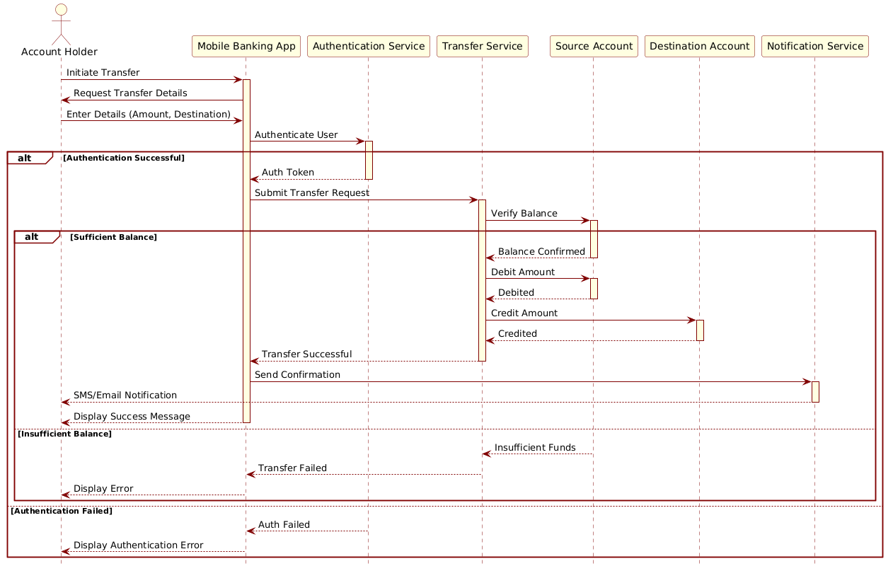
A sequence diagram is a behavioral model that focuses on when interactions occur rather than just what happens. In this Core Banking context, the diagram abstracts the runtime behavior of the system. It maps the lifelines of key participants (such as the Mobile Banking App and the Transfer Service) and visualizes the messages exchanged between them. The activation bars (vertical rectangles on lifelines) indicate when a component is actively processing a request, providing insight into concurrency and processing bottlenecks.
Target Domain Scope & Scenario
This model focuses specifically on the secure fund transfer workflow. It intentionally excludes peripheral processes like account creation or customer onboarding to maintain clarity. The scope covers the critical path: user authentication, balance verification, atomic debiting/crediting operations, and notification delivery. Crucially, it also models the exception paths (e.g., insufficient funds or authentication failure), which are often the most complex parts of financial logic.
Key Takeaways & Educational Insights
By constructing this diagram, you will gain architectural clarity on several fronts:
- Boundary Definition: Clearly separate the client-side interface (Mobile App) from backend services (Auth, Transfer, Notification).
- Conditional Logic: Learn how to represent alternative flows using
altblocks, ensuring all error states are documented. - Resource Management: Understand how
activateanddeactivatekeywords help visualize the duration of service usage and resource locking.
Complete Diagram & Full Source Code
Below is the complete blueprint for the Core Banking Fund Transfer sequence. This code includes the rose.puml theme for a professional aesthetic, defines all necessary actors and participants, and implements the logic for both successful transactions and failure scenarios.
@startuml
!include https://static.visual-paradigm.com/web/resources/plantuml-stdlib/themes/rose.puml

actor "Account Holder" as Holder
participant "Mobile Banking App" as App
participant "Authentication Service" as AuthService
participant "Transfer Service" as TransferService
participant "Source Account" as SrcAccount
participant "Destination Account" as DestAccount
participant "Notification Service" as NotifService

Holder -> App: Initiate Transfer
activate App
App -> Holder: Request Transfer Details
Holder -> App: Enter Details (Amount, Destination)
App -> AuthService: Authenticate User
activate AuthService

alt Authentication Successful
    AuthService --> App: Auth Token
    deactivate AuthService

    App -> TransferService: Submit Transfer Request
    activate TransferService
    TransferService -> SrcAccount: Verify Balance
    activate SrcAccount

    alt Sufficient Balance
        SrcAccount --> TransferService: Balance Confirmed
        deactivate SrcAccount

        TransferService -> SrcAccount: Debit Amount
        activate SrcAccount
        SrcAccount --> TransferService: Debited
        deactivate SrcAccount

        TransferService -> DestAccount: Credit Amount
        activate DestAccount
        DestAccount --> TransferService: Credited
        deactivate DestAccount

        TransferService --> App: Transfer Successful
        deactivate TransferService

        App -> NotifService: Send Confirmation
        activate NotifService
        NotifService --> Holder: SMS/Email Notification
        deactivate NotifService

        App --> Holder: Display Success Message
        deactivate App
    else Insufficient Balance
        SrcAccount --> TransferService: Insufficient Funds
        deactivate SrcAccount
        TransferService --> App: Transfer Failed
        deactivate TransferService
        App --> Holder: Display Error
        deactivate App
    end
else Authentication Failed
    AuthService --> App: Auth Failed
    deactivate AuthService
    App --> Holder: Display Authentication Error
    deactivate App
end
@endumlStep-by-Step Architectural Walkthrough
Building a robust financial sequence diagram requires a structured approach. We will break down the construction of this model into four distinct phases, moving from configuration to logic implementation.
Phase 1: Canvas Configuration & Layout Directives
Every PlantUML diagram begins with setup directives that define the rendering engine and visual style. In this financial context, clarity and professionalism are paramount.
We start with @startuml and @enduml to mark the boundaries of the diagram. Crucially, we include the rose.puml theme provided by Visual Paradigm to ensure the diagram meets enterprise standards without manual CSS styling.
!include https://static.visual-paradigm.com/web/resources/plantuml-stdlib/themes/rose.pumlThis directive pulls in a pre-defined skinparam set that handles font rendering, actor shapes, and message arrow styles, allowing you to focus on the logic rather than aesthetics.
Phase 2: Declaring Core Entities, Actors, and Boundaries
Next, we define the participants involved in the transaction. In PlantUML, we distinguish between actors (human users) and participants (system components).
actor "Account Holder" as Holder
participant "Mobile Banking App" as App
participant "Authentication Service" as AuthService
We assign aliases (e.g., as Holder) to shorten references later in the code. This separation of concerns ensures that the Mobile App acts as the gateway, while the Authentication Service handles security credentials independently. This modularity is critical for maintaining security boundaries in a banking system.
Phase 3: Mapping Data Flows & Key Interactions
With participants declared, we map the chronological flow of messages. We use solid arrows (->) for synchronous requests and dashed arrows (-->) for responses.
App -> AuthService: Authenticate User
activate AuthService
The activate keyword is vital here. It visually indicates that the AuthService is busy processing the request. This helps identify potential blocking points in the system. Once the service completes its task, we use deactivate to return control to the caller, signaling that the resource is released.
Phase 4: Grouping, Annotations & Visual Polish
Financial systems must handle exceptions gracefully. We use the alt (alternative) block to encapsulate conditional logic, such as checking for sufficient funds or successful authentication.
alt Authentication Successful
    ...
else Authentication Failed
    ...
end
Inside the alt block, we can nest another alt block to handle the balance check. This nesting allows us to model complex decision trees clearly. Finally, we ensure every path terminates with a deactivate statement to prevent visual clutter and logical errors in the rendered diagram.
Syntax & Keyword Deep Dive
Understanding the specific PlantUML syntax is essential for creating accurate models. Here is a breakdown of the key keywords used in this Core Banking diagram:
actor: Represents an external human entity interacting with the system (e.g., the Account Holder). It is drawn as a stick figure in the rendered output.participant: Represents a system component, service, or database table (e.g.,TransferService). These are typically drawn as rectangles.->(Arrow): Denotes a synchronous message call. The sender waits for the receiver to process the request.-->(Dashed Arrow): Denotes a return message or response from the receiver back to the sender.activate/deactivate: Controls the visibility of the activation bar on a lifeline.activatestarts the bar, indicating processing time, whiledeactivateends it.alt/else/end: Defines alternative execution paths. Thealtblock represents the primary condition,elserepresents the failure or alternative condition, andendcloses the block.
Best Practices & Pitfalls to Avoid
To ensure your PlantUML diagrams remain maintainable and readable, adhere to these modeling best practices:
- Keep Lifelines Meaningful: Avoid creating too many participants. Group related services (e.g., keep all account operations within the
Accountlifeline) to reduce visual noise. - Consistent Naming: Use clear, domain-specific names for messages (e.g.,
Verify Balanceinstead ofCheck). This makes the diagram readable even for non-technical stakeholders. - Balance Error Handling: Never model only the “Happy Path.” Always include
altblocks for authentication failures and insufficient funds, as these represent the most critical risks in banking. - Manage Complexity: If a diagram becomes too crowded, consider splitting it into multiple diagrams (e.g., one for Authentication, one for the Transfer Logic) rather than cramming everything into one view.
Start Building PlantUML Sequence Diagrams Faster with VPasCode
Instantly prototype, preview, and customize your Core Banking sequence diagrams online without installing any tools or configuring local environments.