


In high-stakes industrial environments like nuclear energy, the margin for error is nonexistent. Clear, unambiguous documentation of system responsibilities and user interactions is not merely a best practice; it is a regulatory and safety imperative. When designing complex control systems, traditional hand-drawn diagrams often fail to capture the precise logic required for safety compliance or become outdated the moment requirements shift. This is where the diagram-as-code paradigm transforms the engineering workflow.
By leveraging PlantUML within the VPasCode browser editor, safety engineers and system architects can create living documentation that is versioned, testable, and instantly renderable. This tutorial focuses on constructing a Use Case Diagram for a Nuclear Power Plant Safety Control System. Unlike standard software applications, this system must rigorously define boundaries between human intervention and automated safety protocols. We will explore how to map primary actors, such as plant operators, and secondary actors, like maintenance engineers, to critical functions including anomaly detection, emergency shutdowns, and containment activation.
The power of this approach lies in its precision. Every association, inclusion, and extension is explicitly coded, eliminating the ambiguity of freehand sketching. Using VPasCode, you can visualize these interactions in real-time, ensuring that the safety logic holds up under scrutiny before it ever reaches the deployment phase. This guide walks you through the architectural decisions and syntax required to build a professional-grade model.
Understanding the Model: Purpose, Scope & Problem Framing
Before writing a single line of code, it is essential to understand the abstraction layer this diagram represents. A Use Case Diagram is a behavioral view that describes the interactions between external entities (actors) and the system itself. It answers the question: “What does the system do, and who does it do it for?” In the context of nuclear safety, this diagram serves as the foundational contract for the Safety Control System.
Diagram Abstraction & Representation
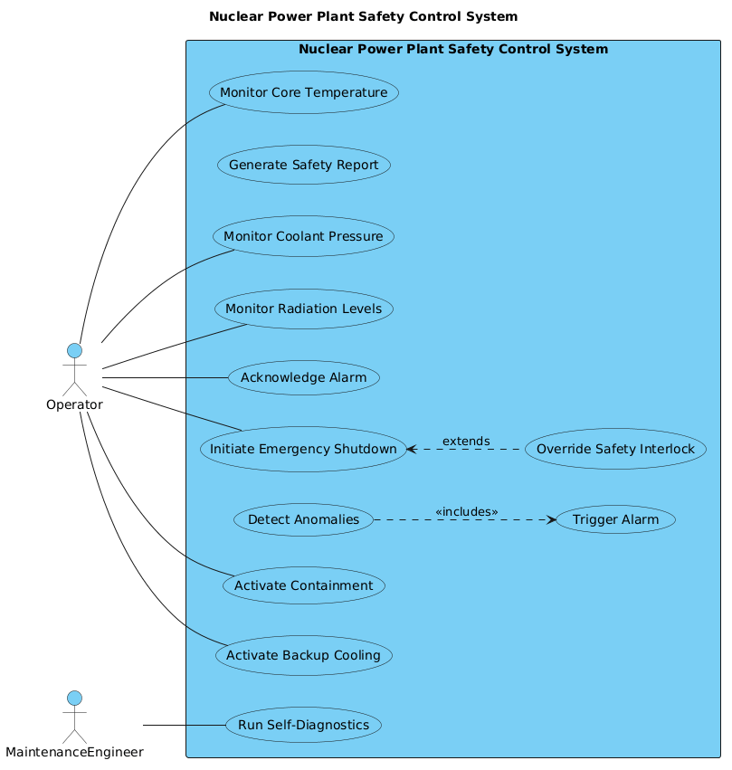
This specific diagram models the functional scope of a critical infrastructure system. The Actor represents a role played by a human or external system that interacts with the software. The Use Case represents a specific goal or function the system performs in response to an actor’s input. The System Boundary (the rectangle) defines the scope of the software being modeled, separating internal logic from external interaction.
Target Domain Scope & Scenario
The scope here is strictly limited to the Nuclear Power Plant Safety Control System. It does not model the physical reactor core itself, but rather the digital layer responsible for monitoring and mitigating risks. The scenario covers continuous monitoring of critical parameters (temperature, pressure, radiation), detection of anomalies, and the execution of safety protocols. We intentionally exclude non-safety administrative functions to maintain focus on the critical path.
Key Takeaways & Educational Insights
By completing this tutorial, you will gain clarity on how to model high-risk interactions without clutter. You will learn how to distinguish between a primary actor who initiates a process and a secondary actor who supports it. Furthermore, you will understand how to use includes and extends relationships to manage complex safety logic, such as mandatory alarm triggers or optional override procedures.
Complete Diagram & Full Source Code
Below is the final rendered output of the diagram we will build. This visualization clearly delineates the Operator’s direct control over monitoring and emergency actions, while highlighting the Maintenance Engineer’s role in diagnostics.
@startuml
!include https://static.visual-paradigm.com/web/resources/plantuml-stdlib/themes/vp.puml

title Nuclear Power Plant Safety Control System

/'
This use case diagram models the functional scope of a Nuclear Power Plant Safety Control System.
The system is responsible for monitoring critical plant parameters, detecting abnormal conditions,
and executing automated safety actions to prevent or mitigate accidents. It ensures continuous
operation within safe limits through redundant sensors, emergency shutdown capabilities, and
containment measures. Operators interact with the system to monitor status, acknowledge alarms,
and manually initiate safety procedures when necessary. External monitoring agencies and
emergency response services receive real-time notifications and data for regulatory compliance
and public safety coordination.
'/

left to right direction

actor "Operator" as Operator

rectangle "Nuclear Power Plant Safety Control System" {
    usecase "Monitor Core Temperature" as UC_MonitorTemp
    usecase "Monitor Coolant Pressure" as UC_MonitorPressure
    usecase "Monitor Radiation Levels" as UC_MonitorRadiation
    usecase "Detect Anomalies" as UC_DetectAnomalies
    usecase "Trigger Alarm" as UC_TriggerAlarm
    usecase "Acknowledge Alarm" as UC_AcknowledgeAlarm
    usecase "Initiate Emergency Shutdown" as UC_EmergencyShutdown
    usecase "Activate Containment" as UC_ActivateContainment
    usecase "Activate Backup Cooling" as UC_BackupCooling
    usecase "Generate Safety Report" as UC_GenerateReport
    usecase "Run Self-Diagnostics" as UC_SelfDiagnostics
    usecase "Override Safety Interlock" as UC_OverrideInterlock
}

Operator -- UC_MonitorTemp
Operator -- UC_MonitorPressure
Operator -- UC_MonitorRadiation
Operator -- UC_AcknowledgeAlarm
Operator -- UC_EmergencyShutdown
Operator -- UC_ActivateContainment
Operator -- UC_BackupCooling

MaintenanceEngineer -- UC_SelfDiagnostics

UC_DetectAnomalies ..> UC_TriggerAlarm : <<includes>>

UC_EmergencyShutdown <.. UC_OverrideInterlock : extends

@endumlStep-by-Step Architectural Walkthrough
Constructing this diagram requires a logical progression from setup to relationship mapping. We will break the build process into four distinct phases to ensure clarity and maintainability.
Phase 1: Canvas Configuration & Layout Directives
Every PlantUML diagram begins with configuration directives that set the visual style and layout. In this model, we import the VPasCode theme to ensure a professional, consistent look that matches the Visual Paradigm ecosystem.
!include https://static.visual-paradigm.com/web/resources/plantuml-stdlib/themes/vp.puml

title Nuclear Power Plant Safety Control System

/'
This use case diagram models the functional scope of a Nuclear Power Plant Safety Control System.
...
'/

left to right direction
The title directive adds a header to the diagram, while the comment block /' ... '/ provides context for anyone reading the source code later. The left to right direction directive forces the layout to flow horizontally, which is often better for complex systems with multiple actors.
Phase 2: Declaring Core Entities, Actors, and Boundaries
Next, we define the actors and the system boundary. The actor keyword defines the human roles. We place the primary actor, Operator, on the left to signify their primary interaction with the system.
actor "Operator" as Operator

rectangle "Nuclear Power Plant Safety Control System" {
    usecase "Monitor Core Temperature" as UC_MonitorTemp
    ...
}
The rectangle creates the system boundary. Inside this box, we define every use case using the usecase keyword. We assign unique aliases (like UC_MonitorTemp) to each use case. This aliasing is crucial for maintaining clean association lines later, preventing long, cluttered lines that connect actor names directly to long use case descriptions.
Phase 3: Mapping Data Flows & Key Interactions
With the entities defined, we establish the relationships. In PlantUML, a simple line -- denotes a standard association. We map the Operator to the monitoring and emergency functions.
Operator -- UC_MonitorTemp
Operator -- UC_EmergencyShutdown

MaintenanceEngineer -- UC_SelfDiagnostics
Note that we do not use arrowheads for standard associations in this style, as the direction is implied by the context. We also ensure that multiple primary actors do not connect to the same use case unless logically necessary, keeping the diagram clean.
Phase 4: Grouping, Annotations & Visual Polish
Finally, we handle complex logic using includes and extends. The includes relationship means one use case is part of another. Here, detecting anomalies must trigger an alarm.
UC_DetectAnomalies ..> UC_TriggerAlarm : <>
Conversely, the extends relationship represents optional behavior. An operator can initiate an emergency shutdown, but there is a specific, extended scenario where they might override a safety interlock to do so.
UC_EmergencyShutdown <.. UC_OverrideInterlock : extends
Syntax & Keyword Deep Dive
Understanding the specific PlantUML syntax is key to mastering VPasCode. Below is a breakdown of the critical keywords used in this nuclear safety model.
title: Sets the main heading of the diagram. Essential for documentation headers.actor: Defines a participant outside the system boundary. Syntax:actor "Name" as Alias.rectangle: Creates the system boundary box. Syntax:rectangle "Name" { ... }.usecase: Defines a specific function or goal within the system boundary. Syntax:usecase "Name" as Alias.--: Represents a standard association (link) between actors and use cases without arrowheads...>: Represents a dependency or relationship with a specific direction.<<includes>>: Indicates that the base use case incorporates the behavior of the included use case.<<extends>>: Indicates that the extending use case adds behavior to the base use case under specific conditions.left to right direction: A layout directive to control the flow of the diagram from left to right.
Best Practices & Pitfalls to Avoid
To ensure your Use Case Diagrams remain effective and maintainable, adhere to these modeling guidelines when using VPasCode.
- Define Clear Boundaries: Always enclose use cases within a system rectangle. This prevents ambiguity about what is internal logic versus external input.
- Use Meaningful Aliases: Never link actors directly to long use case text. Always use aliases (e.g.,
as UC_MonitorTemp) to keep association lines clean and readable. - Limit Complexity: Avoid connecting too many actors to the same use case. If multiple actors perform the same action, consider grouping them or splitting the use case.
- Consistent Notation: Stick to standard PlantUML syntax for associations. Do not mix arrow styles unless you have a specific semantic reason to do so.
Start Building Nuclear Safety Diagrams Faster with VPasCode
Test, preview, and customize this PlantUML Use Case diagram online in VPasCode without installing any tools or configuring environments.