


In the fast-paced retail sector, customer loyalty programs are the backbone of long-term engagement and revenue retention. However, building a robust loyalty platform involves orchestrating multiple complex subsystems: from the initial customer interaction in a mobile app or point-of-sale terminal to the backend logic that calculates points and manages reward fulfillment. Without a clear architectural blueprint, these systems can quickly become entangled, leading to data inconsistencies, slow performance, and difficult maintenance cycles.
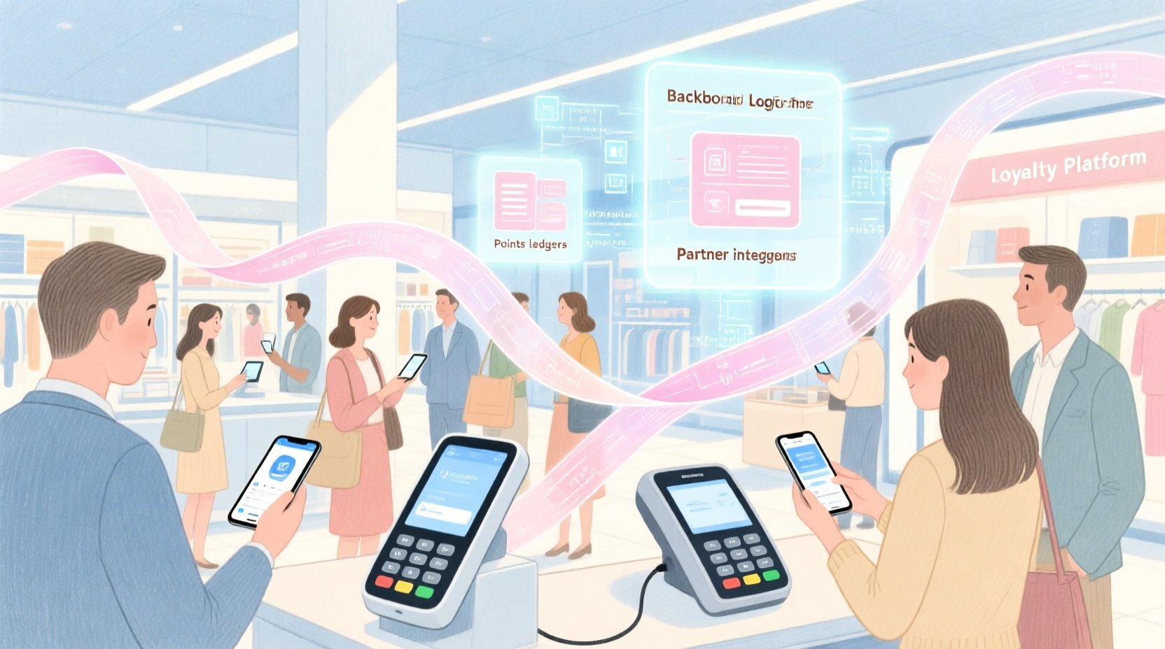
Diagramming-as-code offers a modern solution to this complexity. By using PlantUML within VPasCode, software architects can define the structure of these systems in plain text, ensuring that the documentation stays synchronized with the actual codebase. This approach allows teams to visualize the separation of concerns across different business domains—such as Campaign Management versus Rewards Processing—before a single line of production code is written. It transforms abstract requirements into a tangible, interactive map of dependencies and interfaces.
Understanding the Model: Purpose, Scope & Problem Framing
This tutorial focuses on constructing a Component Diagram, a specific type of PlantUML blueprint used to describe the structural organization of a system. Unlike a class diagram that details internal logic, a component diagram abstracts the system into deployable units, highlighting how they interact via defined interfaces. This level of abstraction is critical for retail architecture where teams often work in silos; the Customer Engagement team needs to know what data the Campaign Engine requires without needing to understand the internal implementation of the Points Ledger.
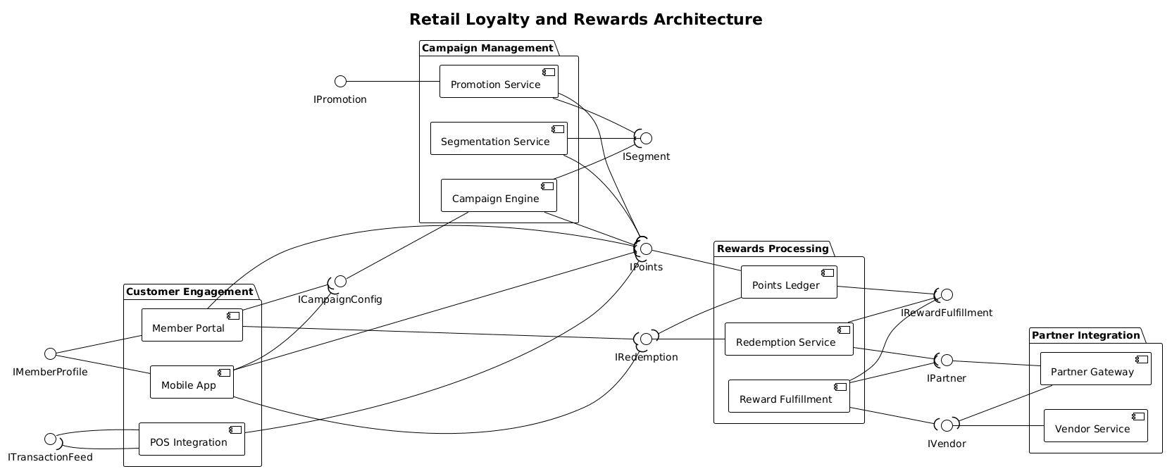
The scope of this diagram covers four logical tiers essential for a modern loyalty platform. The Customer Engagement tier handles the front-end touchpoints like the Member Portal and Mobile App. The Campaign Management tier governs how promotions are created and targeted. The Rewards Processing tier manages the core logic of point accrual and redemption. Finally, the Partner Integration tier ensures the system can scale by connecting with external vendors. By modeling these boundaries, you gain clarity on where data flows begin and end, preventing tight coupling between modules.
Complete Diagram & Full Source Code
Before diving into the step-by-step construction, review the complete blueprint below. This diagram utilizes the ball-and-socket notation to clearly distinguish between services provided by a component (the ball) and services required by a component (the socket). This visual convention is standard in PlantUML for component diagrams and ensures immediate readability for stakeholders.
@startuml
!theme plain
left to right direction

title Retail Loyalty and Rewards Architecture

/'
This component diagram captures the high-level architecture of a retail loyalty and rewards platform.
The system is structured into four logical tiers: Customer Engagement, Campaign Management, Rewards Processing, and Partner Integration.
It highlights how customer interactions trigger points accrual, how campaigns are configured and executed, and how rewards are fulfilled both in-house and through external partners.
The diagram emphasizes clear separation of concerns and interface-based dependencies between core modules.
'/

package "Customer Engagement" {
    component "Member Portal" as MemberPortal
    component "Mobile App" as MobileApp
    component "POS Integration" as POS
}

package "Campaign Management" {
    component "Campaign Engine" as CampaignEngine
    component "Promotion Service" as PromotionService
    component "Segmentation Service" as SegmentationService
}

package "Rewards Processing" {
    component "Points Ledger" as PointsLedger
    component "Reward Fulfillment" as RewardFulfillment
    component "Redemption Service" as RedemptionService
}

package "Partner Integration" {
    component "Partner Gateway" as PartnerGateway
    component "Vendor Service" as VendorService
}

' Provided interfaces (ball on the left)
interface "IMemberProfile" as IMemberProfile
interface "ITransactionFeed" as ITransactionFeed
interface "ICampaignConfig" as ICampaignConfig
interface "IPromotion" as IPromotion
interface "ISegment" as ISegment
interface "IPoints" as IPoints
interface "IRedemption" as IRedemption
interface "IRewardFulfillment" as IRewardFulfillment
interface "IPartner" as IPartner
interface "IVendor" as IVendor

' Required interfaces (socket on the right)

' Customer Engagement provides interfaces
IMemberProfile -- MemberPortal
ITransactionFeed -- POS
IMemberProfile -- MobileApp

' Campaign Management provides interfaces
ICampaignConfig -- CampaignEngine
IPromotion -- PromotionService
ISegment -- SegmentationService

' Rewards Processing provides interfaces
IPoints -- PointsLedger
IRedemption -- RedemptionService
IRewardFulfillment -- RewardFulfillment

' Partner Integration provides interfaces
IPartner -- PartnerGateway
IVendor -- VendorService

' Required interfaces (dependencies)
MemberPortal --( ICampaignConfig
MemberPortal --( IPoints
MemberPortal --( IRedemption

POS --( ITransactionFeed
POS --( IPoints

MobileApp --( ICampaignConfig
MobileApp --( IPoints
MobileApp --( IRedemption

CampaignEngine --( ISegment
CampaignEngine --( IPoints

PromotionService --( ISegment
PromotionService --( IPoints

SegmentationService --( IPoints

PointsLedger --( IRedemption
PointsLedger --( IRewardFulfillment

RedemptionService --( IRewardFulfillment
RedemptionService --( IPartner

RewardFulfillment --( IPartner
RewardFulfillment --( IVendor

PartnerGateway --( IVendor

@endumlStep-by-Step Architectural Walkthrough
Building this diagram in VPasCode requires a logical progression from canvas setup to interface definition. Follow these phases to replicate the architecture accurately.
Phase 1: Canvas Configuration & Layout Directives
Every PlantUML diagram begins with configuration directives that set the rendering engine’s behavior. In this retail architecture, we prioritize a horizontal flow to accommodate the width of package names and interface definitions. We start by declaring the theme and direction.
!theme plain
left to right direction
The !theme plain directive ensures a clean, minimalist look without default styling that might distract from the architectural relationships. The left to right direction directive aligns the packages horizontally, which is standard for system architecture diagrams where data flows from left (input/customer) to right (backend processing).
Phase 2: Declaring Core Entities, Actors, and Boundaries
The next step is defining the system boundaries using package blocks. In VPasCode, packages act as logical containers that group related components. This is crucial for the retail domain to separate concerns like Campaign Management from Rewards Processing.
package "Customer Engagement" {
    component "Member Portal" as MemberPortal
    component "Mobile App" as MobileApp
    component "POS Integration" as POS
}
Notice the syntax component "Name" as Alias. The string inside quotes is the human-readable label displayed in the diagram, while the as Alias part creates a shorthand reference used later for connecting lines. This separation allows you to change the display name without breaking your connection logic.
Phase 3: Mapping Data Flows & Key Interactions
Once components are defined, we must declare the interfaces they expose or require. In PlantUML component diagrams, interfaces are represented by the interface keyword. We define all interfaces globally before connecting them to ensure clarity.
interface "IMemberProfile" as IMemberProfile
interface "ICampaignConfig" as ICampaignConfig
After declaration, we map the relationships. A provided interface (a service offered by a component) uses a solid line with a ball on the provider side. A required interface (a dependency) uses a solid line with a socket on the consumer side. For example, the Member Portal requires Campaign Configuration:
MemberPortal --( ICampaignConfigThe --( syntax indicates that MemberPortal needs the ICampaignConfig interface to function. This visual cue immediately tells the reader that the Portal cannot operate without this specific configuration service.
Phase 4: Grouping, Annotations & Visual Polish
To finalize the diagram, we add a title and a context description using a comment block. This provides immediate context for anyone viewing the diagram in VPasCode without needing external documentation.
title Retail Loyalty and Rewards Architecture

/'
This component diagram captures the high-level architecture...
'/
The /' ... '/ syntax wraps a multi-line comment that renders as a note below the title. This is excellent for explaining the diagram’s scope, such as noting that the system handles both in-house rewards and external partner integrations.
Syntax & Keyword Deep Dive
Understanding the specific PlantUML syntax used in this tutorial is essential for mastering component diagrams. Below are the key keywords and conventions employed in the Retail Loyalty architecture.
package: Defines a logical grouping of components. It allows you to organize the diagram into functional tiers like “Customer Engagement” or “Partner Integration”.component: Represents a deployable unit of software. In this diagram, components like “Points Ledger” represent specific microservices or modules.interface: Defines a contract of functionality. Interfaces likeIPointsorIRedemptionspecify what operations are available without revealing how they are implemented.--(Provided Interface): Connects a component to the interface it provides. The ball (socket) appears on the component side, indicating the service is offered here.--((Required Interface): Connects a component to the interface it requires. The socket (ball) appears on the interface side, indicating the component needs this service.!theme: Sets the visual style of the diagram.!theme plainremoves decorative elements for a cleaner technical look./'&'/: These characters wrap multi-line comments that render as text annotations within the diagram.
Best Practices & Pitfalls to Avoid
When building component diagrams for complex systems like retail loyalty platforms, adhering to best practices ensures the diagram remains maintainable and useful over time.
1. Maintain Consistent Interface Naming: Always prefix interface names with I (e.g., IMemberProfile) to distinguish them from components. This visual distinction helps readers quickly identify dependencies versus implementations.
2. Avoid Circular Dependencies: In the walkthrough, ensure that components do not require each other in a way that creates a loop (A needs B, B needs A) unless absolutely necessary for the architecture. Use the --( syntax to explicitly visualize these flows and check for cycles.
3. Use Descriptive Aliases: When defining components, use short aliases (e.g., as MemberPortal) for the connection lines. This keeps the code clean and makes the connection lines easier to read than long package names.
4. Leverage Packages for Scale: As your system grows, do not clutter a single canvas. Use packages to group related components. If a diagram becomes too complex, consider splitting it into multiple diagrams (e.g., one for Customer Engagement, one for Backend Processing) and linking them.
Start Building Retail Loyalty Diagrams Faster with VPasCode
Instantly prototype your architecture with live browser preview, zero local installation, and interactive syntax testing for free in VPasCode.