


Introduction: Visualizing Recurring Billing Workflows
In the financial technology sector, clarity is currency. When designing a Recurring Billing System, the logic governing customer mandates and payment schedules must be precise. A single misinterpretation in the flow of a Standing Order setup can lead to compliance issues, failed payments, or customer dissatisfaction. This is where diagram-as-code becomes an indispensable asset for software architects and developers.
Sequence diagrams are the industry standard for modeling runtime interactions between system components. By using PlantUML within VPasCode, you can define these complex financial workflows in text, render them instantly in the browser, and iterate rapidly without the friction of dragging and dropping boxes. This tutorial serves as a masterclass in constructing a robust sequence diagram that captures the nuances of validating customer accounts, generating payment mandates, and storing order details securely.
Understanding the Model: Purpose, Scope & Problem Framing
Diagram Abstraction & Representation
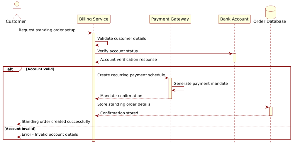
A Sequence Diagram focuses on the when and how of interactions. Unlike a class diagram that defines structure, or a flowchart that defines logic, a sequence diagram maps the temporal flow of messages between objects. In this model, we represent:
- Lifelines: The persistent entities such as the Customer, Billing Service, and Database.
- Messages: The synchronous and asynchronous calls that trigger actions (e.g., “Request standing order setup”).
- Activation Bars: Periods during which an object is performing an action.
This visual abstraction is critical for finance because it exposes the exact sequence of validation checks before money is committed. It answers the question: “Does the system verify the bank account before asking the Payment Gateway to create a mandate?”
Target Domain Scope & Scenario
The scope of this diagram is strictly limited to the Standing Order Setup lifecycle. It does not cover the actual execution of the payment (the recurring cycle), but rather the initialization phase. The boundaries include the external Customer actor, the internal Billing Service, external dependencies like the Payment Gateway and Bank Account, and the internal Order Database. This separation ensures that the architecture clearly distinguishes between internal state management and external API contracts.
Key Takeaways & Educational Insights
By mastering this diagram, you will gain insights into:
- Guarding Critical Operations: How to model validation steps (Account Valid vs. Invalid) using combined fragments.
- Resource Management: The use of
activateanddeactivateto visualize when services are busy or waiting. - External Dependencies: Properly modeling interactions with third-party financial APIs like Payment Gateways.
Complete Diagram & Full Source Code
Below is the finished blueprint for the Standing Order Setup workflow. This diagram utilizes the Rose theme for a professional, clean aesthetic suitable for technical documentation.
Copy the complete source code below to start editing immediately in VPasCode:
@startuml
!include https://static.visual-paradigm.com/web/resources/plantuml-stdlib/themes/rose.puml

actor Customer as C
participant "Billing Service" as BS
participant "Payment Gateway" as PG
participant "Bank Account" as BA
database "Order Database" as DB

C -> BS: Request standing order setup
activate BS
BS -> BS: Validate customer details
BS -> BA: Verify account status
activate BA
BA --> BS: Account verification response
deactivate BA

alt Account Valid
    BS -> PG: Create recurring payment schedule
    activate PG
    PG -> PG: Generate payment mandate
    PG --> BS: Mandate confirmation
    deactivate PG

    BS -> DB: Store standing order details
    activate DB
    DB --> BS: Confirmation stored
    deactivate DB

    BS --> C: Standing order created successfully
else Account Invalid
    BS --> C: Error - Invalid account details
end

deactivate BS
@endumlStep-by-Step Architectural Walkthrough
Building this diagram in VPasCode is a linear process of defining entities, connecting them, and refining the logic. Follow these phases to replicate the architecture.
Phase 1: Canvas Configuration & Layout Directives
Every PlantUML diagram begins with directives that set the environment. We start by including the Rose theme to ensure the diagram looks polished immediately.
@startuml
!include https://static.visual-paradigm.com/web/resources/plantuml-stdlib/themes/rose.puml
The @startuml tag signals the beginning of the diagram definition, while the !include directive fetches the styling definitions from the Visual Paradigm server. This ensures consistent colors and shapes without manual CSS configuration.
Phase 2: Declaring Core Entities, Actors, and Boundaries
Next, we define the participants. In a sequence diagram, we distinguish between human actors and system components.
actor Customer as C
participant "Billing Service" as BS
participant "Payment Gateway" as PG
participant "Bank Account" as BA
database "Order Database" as DB
We use specific keywords to render the correct icons:
actor: Represents the external user initiating the process.participant: Represents software services or API endpoints.database: Represents persistent storage systems.
Aliases (like as C) are crucial for brevity in later message definitions, allowing us to write C -> BS instead of repeating long names.
Phase 3: Mapping Data Flows & Key Interactions
This is the core logic of the diagram. We model the synchronous request from the customer and the subsequent validation.
C -> BS: Request standing order setup
activate BS
BS -> BS: Validate customer details
BS -> BA: Verify account status
activate BA
BA --> BS: Account verification response
deactivate BA
Notice the use of -> for synchronous calls and --> for return messages. The activate and deactivate commands create the vertical “activation bars” on the lifelines, visually indicating when the Billing Service is processing the request versus when it is idle.
Phase 4: Grouping, Annotations & Visual Polish
Complex workflows often involve branching logic. Here, we use the alt (alternative) combined fragment to handle the success and failure paths of the account validation.
alt Account Valid
    [Success Path Logic]
else Account Invalid
    [Failure Path Logic]
end
This structure ensures that the diagram clearly communicates that the system behaves differently based on the outcome of the Verify account status check. If valid, we proceed to the Payment Gateway and Database; if invalid, we return an error immediately.
Syntax & Keyword Deep Dive
Understanding the specific PlantUML syntax allows you to expand this diagram for other use cases. Here is a breakdown of the critical keywords used:
actor: Defines a human user or external system interacting with the application. Rendered as a stick figure.participant: Defines a logical component, service, or class. Rendered as a cylinder or box depending on the theme.->(Solid Arrow): Represents a synchronous message or method call. The sender waits for a response.-->(Dashed Arrow): Represents an asynchronous message or a return response.activate/deactivate: Controls the visual representation of the execution lifeline.activatestarts the bar;deactivateends it.alt/else/end: Defines a combined fragment for alternative flows. This is essential for modeling error handling and conditional logic in finance workflows.
Best Practices & Pitfalls to Avoid
When creating sequence diagrams for financial systems, adhere to these architectural guidelines:
- Maintain Abstraction Levels: Do not model every internal function call (e.g., database connection pooling). Focus on the business-level interactions between services.
- Consistent Naming: Use the aliases defined at the top (
as BS) consistently. Inconsistent naming makes the diagram harder to read and maintain. - Visual Balance: Keep the flow left-to-right. If a message goes back and forth too many times, consider grouping it into a nested sequence or breaking it into a separate diagram.
- Clear Error Paths: Never omit the
elsebranch in validation flows. In finance, handling the “Invalid Account” scenario is as important as the success path.
Try It Yourself with VPasCode
Start Building PlantUML Sequence Diagrams Faster with VPasCode
Instantly prototype and validate your finance workflow logic with live browser rendering, zero local installation, and interactive syntax testing.