2. Standard Unified Modeling Language (UML) Diagrams
At its core, PlantUML was built to simplify the creation of official UML diagrams. It separates into two main categories: structural and behavioral diagrams.
Structure Diagrams
Class & Object Diagrams
Model object-oriented structures, class hierarchies, interfaces, attributes, and relationships (inheritance, aggregation, composition) directly from code definitions.
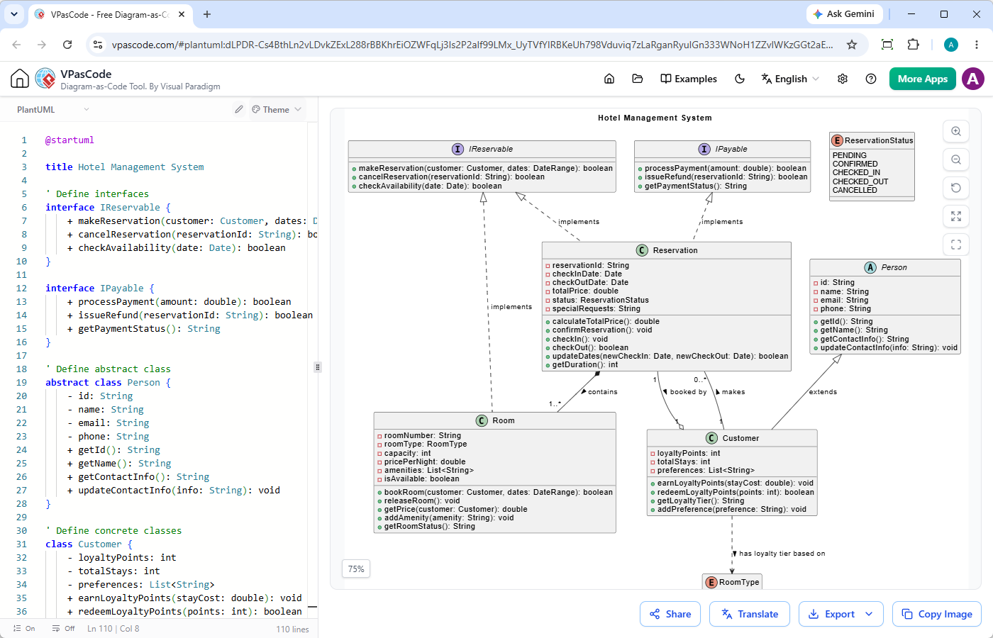
@startuml

title Hotel Management System

' Define interfaces
interface IReservable {
    + makeReservation(customer: Customer, dates: DateRange): boolean
    + cancelReservation(reservationId: String): boolean
    + checkAvailability(date: Date): boolean
}

interface IPayable {
    + processPayment(amount: double): boolean
    + issueRefund(reservationId: String): boolean
    + getPaymentStatus(): String
}

' Define abstract class
abstract class Person {
    - id: String
    - name: String
    - email: String
    - phone: String
    + getId(): String
    + getName(): String
    + getContactInfo(): String
    + updateContactInfo(info: String): void
}

' Define concrete classes
class Customer {
    - loyaltyPoints: int
    - totalStays: int
    - preferences: List
    + earnLoyaltyPoints(stayCost: double): void
    + redeemLoyaltyPoints(points: int): boolean
    + getLoyaltyTier(): String
    + addPreference(preference: String): void
}

class Room {
    - roomNumber: String
    - roomType: RoomType
    - capacity: int
    - pricePerNight: double
    - amenities: List
    - isAvailable: boolean
    + bookRoom(customer: Customer, dates: DateRange): boolean
    + releaseRoom(): void
    + getPrice(customer: Customer): double
    + addAmenity(amenity: String): void
    + getRoomStatus(): String
}

class Reservation {
    - reservationId: String
    - checkInDate: Date
    - checkOutDate: Date
    - totalPrice: double
    - status: ReservationStatus
    - specialRequests: String
    + calculateTotalPrice(): double
    + confirmReservation(): void
    + checkIn(): void
    + checkOut(): boolean
    + updateDates(newCheckIn: Date, newCheckOut: Date): boolean
    + getDuration(): int
}

' Enumeration
enum RoomType {
    STANDARD
    DELUXE
    SUITE
    PRESIDENTIAL
}

' Enumeration
enum ReservationStatus {
    PENDING
    CONFIRMED
    CHECKED_IN
    CHECKED_OUT
    CANCELLED
}

' Relationships
' Interface implementation (dashed line with triangle)
IReservable <|.. Reservation : implements
IPayable <|.. Reservation : implements

' Abstract inheritance (solid line with triangle)
Person <|-- Customer : extends ' Composition (solid diamond) - Room is part of Reservation Reservation *-- "1..*" Room : contains >

' Association (simple solid line) with multiplicity
Customer "1" -- "0..*" Reservation : makes >

' Dependency (dashed arrow) - Customer depends on RoomType
Customer ..> RoomType : has loyalty tier based on >

' Association with custom label
Reservation "1" --o "1" Customer : booked by >

' Realization of interface by abstract class (optional additional connector)
IReservable <|.. Room : implements

@endumlComponent & Deployment Diagrams
Map software components, physical nodes, artifacts, and deployment environments to visualize software distribution across hardware or cloud infrastructure.
@startuml
title Web Application Component Diagram

package "Client Layer" {
    [Web Browser] as Browser
    [Mobile App] as Mobile
}

package "Application Server" {
    [API Gateway] as Gateway
    [User Service] as UserService
    [Order Service] as OrderService
    [Payment Service] as PaymentService
}

package "Database Layer" {
    database "User Database" as UserDB
    database "Order Database" as OrderDB
}

package "Third-Party Services" {
    [Stripe API] as Stripe
}

' Connections
Browser --> Gateway : HTTP / REST
Mobile --> Gateway : HTTP / REST

Gateway --> UserService : Internal REST
Gateway --> OrderService : Internal REST

UserService --> UserDB : Read / Write
OrderService --> OrderDB : Read / Write
OrderService --> PaymentService : Process Payment

PaymentService --> Stripe : HTTPS / API
@enduml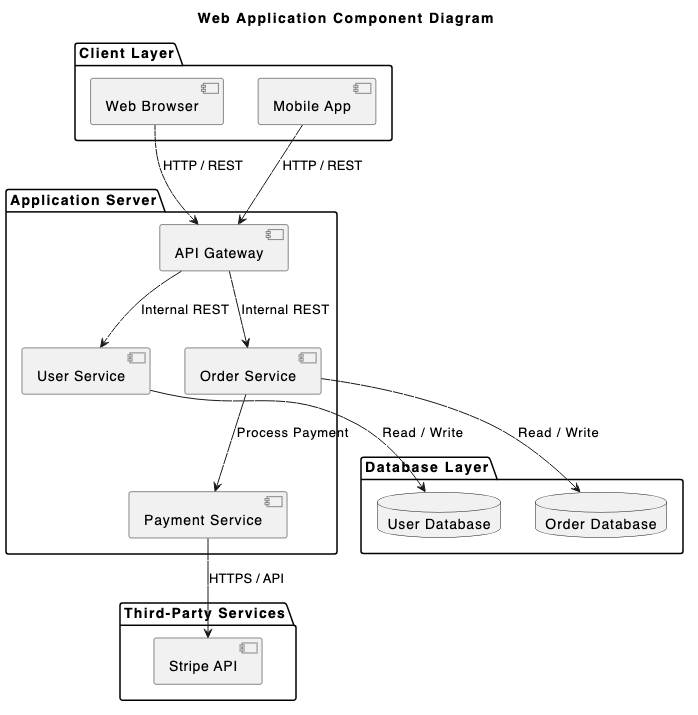
@startuml
title Deployment Diagram - 3-Tier Web Application

skinparam componentStyle rectangle

node "Client Desktop" as clientNode {
  node "Web Browser" as browser {
    artifact "Web App Frontend (HTML/JS)" as frontend
  }
}

node "Application Server" as appServerNode {
  node "Servlet Container (Tomcat)" as tomcat {
    artifact "Backend API (WAR file)" as appApi
  }
}

node "Database Server" as databaseNode {
  database "PostgreSQL" as postgres {
    artifact "Application Database Schema" as dbSchema
  }
}

clientNode -- appServerNode : HTTPS (Port 443)
appServerNode -- databaseNode : JDBC (Port 5432)

@enduml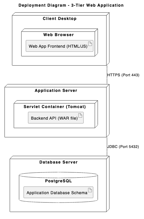
Behavioral & Interaction Diagrams
Sequence Diagrams
The most popular PlantUML diagram type. Trace step-by-step interactions, synchronous/asynchronous API calls, and message flows between actors and systems over time.
@startuml
title User Authentication Flow

actor "User" as user
participant "Web App" as app
participant "Auth API" as auth
database "User DB" as db

user -> app : Enter Credentials
activate app

app -> auth : POST /api/v1/login
activate auth

auth -> db : Query user by email
activate db
db --> auth : Return user record & hash
deactivate db

alt Valid Credentials
    auth -> auth : Verify password & generate JWT
    auth --> app : 200 OK (Token & Profile)
    app --> user : Redirect to Dashboard
else Invalid Credentials
    auth --> app : 401 Unauthorized (Error)
    app --> user : Display "Invalid Credentials"
end

deactivate auth
deactivate app
@enduml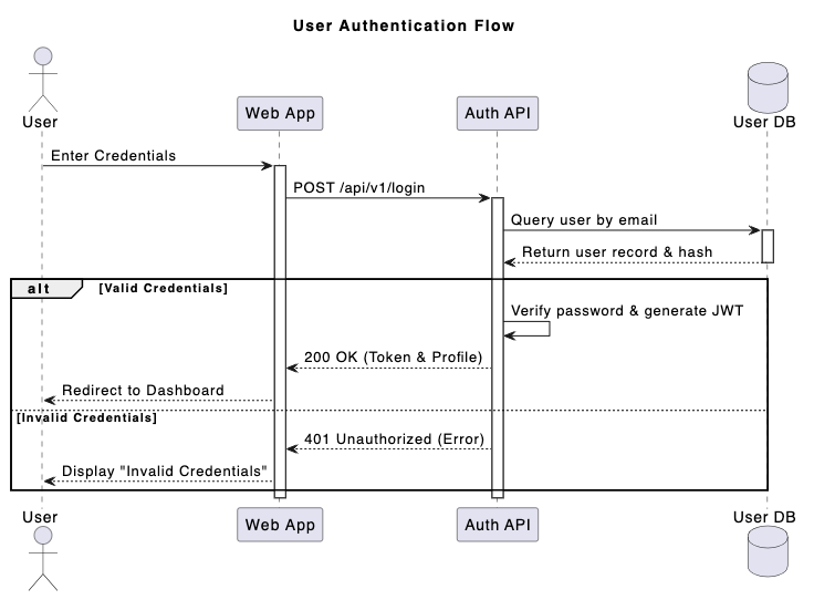
Use Case Diagrams
Define system boundaries, actors, user goals, and functional scope.
@startuml
title Online Shopping System - Use Case Diagram

left to right direction

actor Customer
actor "Registered Customer" as RegCustomer
actor "Payment Gateway" as PaymentSystem

Customer <|-- RegCustomer rectangle "E-Commerce System" { usecase "Browse Products" as UC_Browse usecase "Search Items" as UC_Search usecase "Manage Cart" as UC_Cart usecase "Checkout Order" as UC_Checkout usecase "Apply Discount Coupon" as UC_Coupon usecase "Process Payment" as UC_Payment usecase "View Order History" as UC_History } Customer --> UC_Browse
Customer --> UC_Search
Customer --> UC_Cart
Customer --> UC_Checkout

RegCustomer --> UC_History

UC_Checkout .> UC_Payment : <>
UC_Checkout <.. UC_Coupon : <>

UC_Payment -- PaymentSystem
@enduml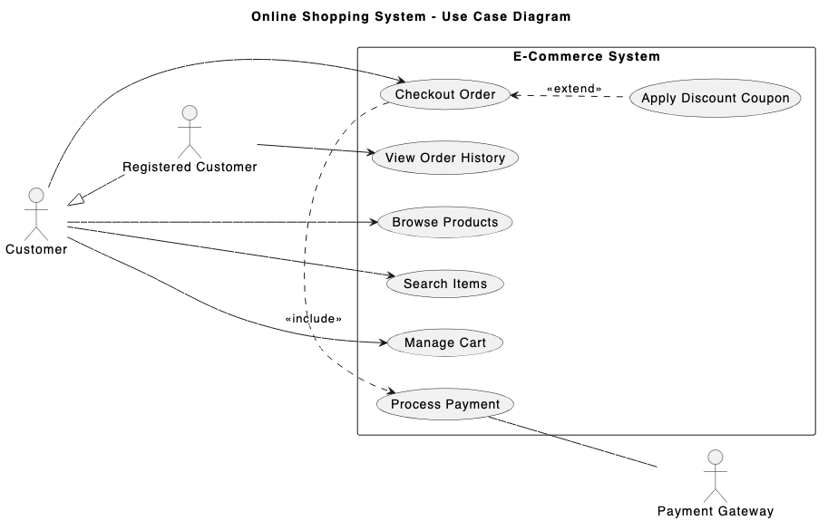
Activity & State Diagrams
Flowchart complex business logic, algorithmic flows, state machine transitions, and concurrency.
@startuml
title Order Fulfillment Process

|Customer|
start
:Place Order;
:Submit Payment Details;

|Order System|
if (Payment Valid?) then (yes)
  :Reserve Inventory;

  ' Concurrency split
  fork
    |Warehouse|
    :Pick Items from Shelf;
    :Pack Items into Box;
  fork again
    |Billing|
    :Generate Invoice PDF;
    :Charge Payment Method;
  end fork

  |Shipping|
  :Attach Shipping Label;
  :Hand Over to Courier;

  |Customer|
  :Receive Package;
  stop
else (no)
  |Order System|
  :Send Payment Failure Notice;
  |Customer|
  :Update Payment Method;
  stop
endif
@enduml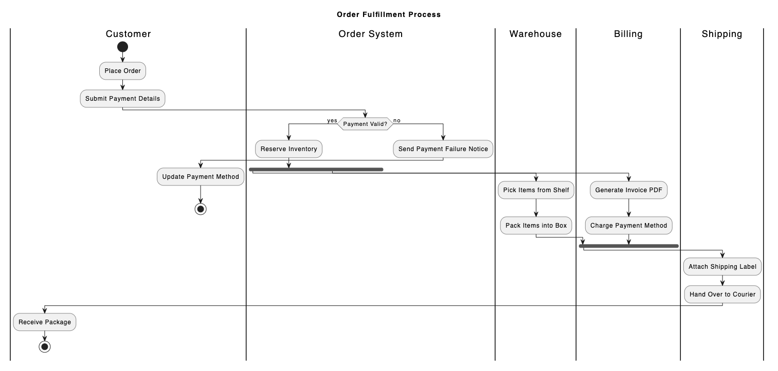
@startuml
title E-Commerce Order Lifecycle

[*] --> Pending : Order Placed

state Pending {
  [*] --> AwaitingPayment
  AwaitingPayment --> PaymentFailed : Payment Error
  PaymentFailed --> AwaitingPayment : Retry Payment
}

Pending --> Processing : Payment Authorized
Pending --> Cancelled : User Cancels Order

state Processing {
  [*] --> Packing
  Packing --> ReadyForShipment : Quality Check Passed
}

Processing --> Shipped : Carrier Handover
Shipped --> Delivered : Delivery Confirmed
Shipped --> Returned : Delivery Failed / Refused

Delivered --> [*]
Cancelled --> [*]
Returned --> [*]
@enduml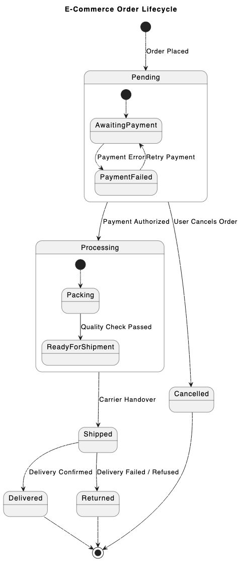
Timing Diagrams
Detail precise state transitions and object interactions over discrete time frames—ideal for embedded systems or real-time hardware design.
@startuml
title SPI Data Transfer Timing Diagram

robust "Clock (SCLK)" as CLK
binary "Chip Select (CS)" as CS
binary "Master Out (MOSI)" as MOSI
concise "Data Bus (MISO)" as MISO

@0
CS is High
CLK is Low
MOSI is Low
MISO is "Idle"

@1
CS is Low
MISO is "Header"

@2
CLK is High
MOSI is High

@3
CLK is Low

@4
CLK is High
MOSI is Low
MISO is "Payload"

@5
CLK is Low

@6
CS is High
CLK is Low
MOSI is Low
MISO is "Idle"

@enduml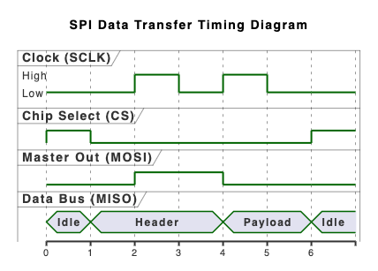
3. High-Level Architecture & Domain-Specific Diagrams
Beyond traditional UML, PlantUML excels at representing multi-layered software systems and data architectures using specialized extension libraries.
C4 Model Diagrams
Express software architecture at varying levels of abstraction—Context, Container, Component, and Code—making system design understandable for both technical and non-technical stakeholders.
@startuml
!include https://raw.githubusercontent.com/plantuml-stdlib/C4-PlantUML/master/C4_Context.puml

TITLE System Context Diagram for Internet Banking System

Person(customer, "Personal Banking Customer", "A customer of the bank, with personal bank accounts.")
System(banking_system, "Internet Banking System", "Allows customers to view information about their bank accounts, and make payments.")

System_Ext(mainframe, "Mainframe Banking System", "Stores all of the core banking information about customers, accounts, transactions, etc.")
System_Ext(email_system, "E-mail System", "The internal Microsoft Exchange e-mail system.")

Rel(customer, banking_system, "Views account balances, and makes payments using")
Rel(banking_system, mainframe, "Gets account information from, and makes payments using")
Rel(banking_system, email_system, "Sends e-mail using")
Rel_Back(email_system, customer, "Sends e-mails to")
@enduml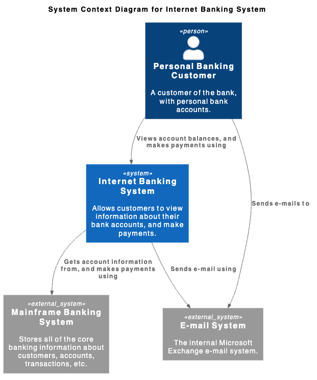
ArchiMate Diagrams
Support enterprise architecture modeling across business, application, and technology layers to map organizational strategy to operational systems.
@startuml
!include <archimate/Archimate>

title ArchiMate Sample - Online Bill Payment

Grouping(business, "Business Layer"){
  Business_Process(payBillProcess, "Pay Bill Process")
  Business_Object(bankAccount, "Customer Bank Account")
  Business_Service(paymentService, "Bill Payment Business Service")
}

Grouping(application, "Application Layer"){
  Application_Component(bankingApp, "Mobile Banking Application")
  Application_Function(paymentProcessing, "Process Payment Logic")
  Application_DataObject(transactionRecord, "Transaction Data Payload")
}

Grouping(technology, "Technology Layer"){
  Technology_Artifact(jwtToken, "Encrypted Session Token")
  Technology_Service(apiGateway, "API Gateway Service")
  Technology_Service(dbService, "Core Database Service")
}

Rel_Flow_Right(payBillProcess, bankAccount, "")
Rel_Serving_Up(paymentService, payBillProcess, "")
Rel_Specialization_Up(paymentProcessing, paymentService, "")
Rel_Flow_Right(transactionRecord, paymentProcessing, "")
Rel_Assignment_Left(bankingApp, paymentProcessing, "")
Rel_Realization_Up(jwtToken, transactionRecord, "")
Rel_Serving_Up(apiGateway, paymentProcessing, "")
Rel_Serving_Up(dbService, apiGateway, "")
@enduml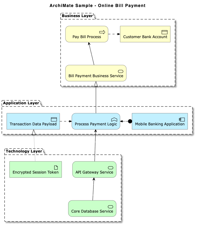
Entity-Relationship Diagrams (ERD)
Generate clean database schema visualizations, including standard crow’s foot notation and Chen ERD models.
@startuml
title E-Commerce Database Schema (Crow's Foot)

' Hide circle icons for entities
hide circle
skinparam linetype ortho

entity "User" as user {
  * user_id : INT <>
  --
  * email : VARCHAR(255)
  * password_hash : VARCHAR(255)
  * created_at : TIMESTAMP
}

entity "CustomerProfile" as profile {
  * profile_id : INT <>
  --
  * user_id : INT <>
  * first_name : VARCHAR(100)
  * last_name : VARCHAR(100)
    phone : VARCHAR(20)
}

entity "Order" as order {
  * order_id : INT <>
  --
  * user_id : INT <>
  * order_date : TIMESTAMP
  * total_amount : DECIMAL(10,2)
  * status : VARCHAR(50)
}

entity "OrderItem" as item {
  * order_item_id : INT <>
  --
  * order_id : INT <>
  * product_id : INT <>
  * quantity : INT
  * unit_price : DECIMAL(10,2)
}

entity "Product" as product {
  * product_id : INT <>
  --
  * sku : VARCHAR(50)
  * name : VARCHAR(150)
    description : TEXT
  * price : DECIMAL(10,2)
}

' Relationships
user ||--o| profile : "has"
user ||--o{ order : "places"
order ||--|{ item : "contains"
product ||--o{ item : "appears in"

@enduml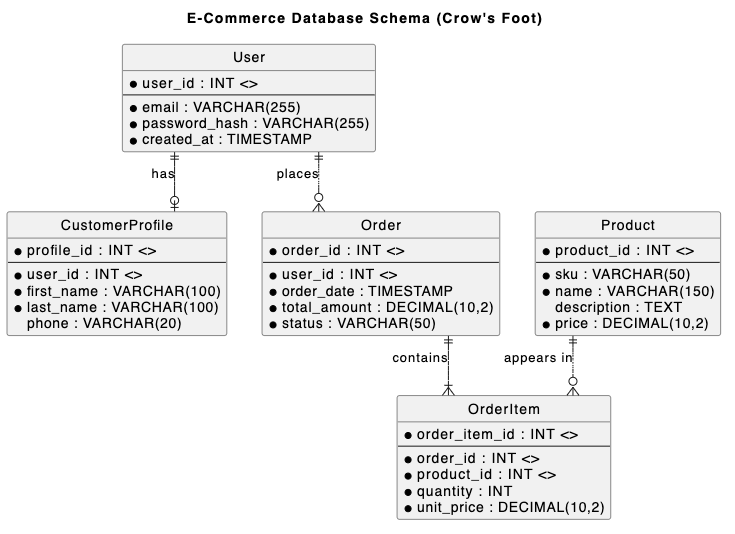
Network & Infrastructure Maps
Render network topologies, server nodes, cloud connections, and firewalls effortlessly.
@startnwdiag
title Enterprise Network Topology

nwdiag {
  network External_Internet {
    address = "0.0.0.0/0"
    user_client [address = "203.0.113.15", description = "Remote User"];
    edge_firewall [address = "192.168.1.1", description = "Perimeter FW"];
  }

  network DMZ_Zone {
    address = "192.168.1.0/24"
    edge_firewall;
    load_balancer [address = "192.168.1.10", description = "Nginx Load Balancer"];
    mail_server [address = "192.168.1.25", description = "SMTP Server"];
    internal_firewall [address = "192.168.1.254", description = "Internal FW"];
  }

  network Private_LAN {
    address = "10.0.1.0/24"
    internal_firewall;
    app_server_01 [address = "10.0.1.50", description = "API Node 1"];
    app_server_02 [address = "10.0.1.51", description = "API Node 2"];
    db_master [address = "10.0.1.100", description = "PostgreSQL Primary"];
  }

  network Management_Subnet {
    address = "10.0.99.0/24"
    internal_firewall;
    admin_bastion [address = "10.0.99.5", description = "SSH Bastion Host"];
    monitoring_node [address = "10.0.99.20", description = "Prometheus Host"];
  }
}
@endnwdiag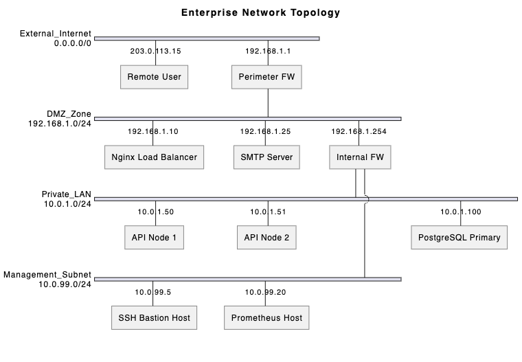
4. Planning, Management & Brainstorming Visuals
PlantUML isn’t restricted to software design—it is also a powerful tool for project management and team brainstorming.
Gantt Charts
Plan project schedules, task dependencies, milestones, and resource allocation using clean text markup.
gantt
    title Software Product Release Schedule
    dateFormat  YYYY-MM-DD
    axisFormat  %b %d

    section Planning & Design
    Requirements Gathering   :a1, 2026-09-01, 10d
    Architecture Design      :a2, after a1, 10d

    section Development
    Backend API Development  :b1, after a2, 15d
    Frontend UI Development  :b2, after a2, 15d

    section Testing & Release
    Integration Testing      :c1, after b1 b2, 8d
    Security Audit           :c2, after c1, 5d
    Production Release       :milestone, m1, after c2, 0d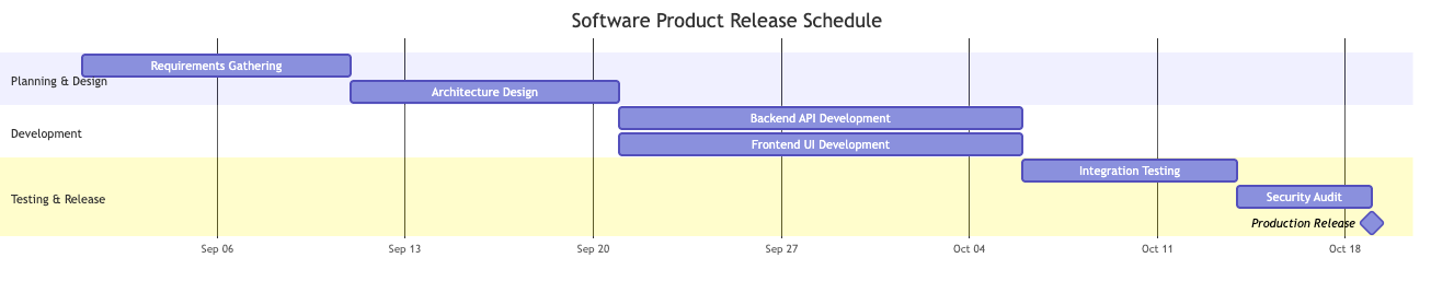
Work Breakdown Structure (WBS)
Deconstruct complex projects into hierarchical deliverables and manageable task chunks.
@startwbs
title Website Redesign WBS

* Website Redesign Project
** 1. Discovery & Strategy
*** 1.1 Stakeholder Interviews
*** 1.2 Competitor Audit
*** 1.3 Scope & Strategy Sign-off
** 2. UX/UI Design
*** 2.1 Wireframing
**** 2.1.1 Desktop Layouts
**** 2.1.2 Mobile Layouts
*** 2.2 Design System
**** 2.2.1 Component Library
**** 2.2.2 Typography & Style Guide
** 3. Technical Development
*** 3.1 Frontend
**** 3.1.1 Page Templates
**** 3.1.2 API Integrations
*** 3.2 CMS & Backend
**** 3.2.1 Custom Post Types
**** 3.2.2 Database Migration
** 4. QA & Launch
*** 4.1 Cross-Browser Testing
*** 4.2 Content Migration
*** 4.3 DNS Cutover & Go-Live
@endwbs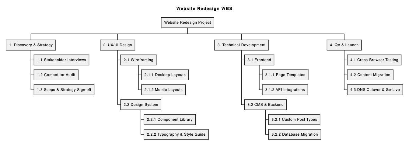
Mind Maps
Capture structured ideas, feature taxonomies, and technical exploration notes rapidly during team sessions.
@startmindmap
title E-Commerce Platform Feature Map

* E-Commerce Platform
** User Account Management
*** Social Auth (Google, Apple)
*** Multi-Factor Authentication
*** Order History & Tracking
** Product Catalog & Search
*** Faceted Search & Filters
*** Inventory Sync
*** Product Reviews & Ratings
** Checkout & Payments
*** Payment Gateways (Stripe, PayPal)
*** Coupon & Promo Engine
*** One-Click Guest Checkout
** Customer Support
*** Live Chat Assistant
*** Automated Return Portal
@endmindmap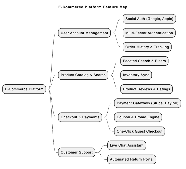
5. Writing and Rendering PlantUML Fast: The VPasCode Advantage
While PlantUML is immensely capable, setting up local Java environments, Graphviz dependencies, and command-line tools can create friction. Using a dedicated, web-based PlantUML Tool eliminates these hurdles completely.
Visual Paradigm VPasCode is a unified diagram-as-code platform engineered specifically to streamline text-to-diagram workflows.
Key Benefits of VPasCode:
- Zero-Setup Online Platform: Access a robust editor instantly at vpascode.com without installing local compilers or plugins. Discover more in the VPasCode Overview.
- Automatic Format Detection & Real-Time Preview: Paste your script, and VPasCode automatically detects whether it’s PlantUML, Mermaid, or Graphviz, rendering live updates instantly as you type.
- AI-Powered Code Error Fixing: If you hit a syntax bug, simply click “Fix by AI”. VPasCode repairs the code and provides a side-by-side diff with clear explanations so you can master PlantUML syntax faster.
- Native AI Diagram Translation: Translate diagram labels and notes into multiple languages directly inside the editor—ideal for global development teams.
- Flexible Export & Documentation Integration: Export high-resolution PNGs or scalable SVG vector images for free. You can also push diagrams directly to Visual Paradigm OpenDocs using their diagram-as-code feature guide.
6. Quick Start Example: Rendering a Sequence Diagram in VPasCode
To see how easy it is to use a free UML editor like VPasCode, consider this basic PlantUML sequence diagram script:
@startuml
autonumber
actor User
participant "VPasCode Editor" as Editor
participant "AI Engine" as AI

User -> Editor: Paste PlantUML Code
Editor -> Editor: Auto-detect Format & Live Render
alt Syntax Error Detected
    User -> Editor: Click "Fix by AI"
    Editor -> AI: Send Broken Code
    AI --> Editor: Return Corrected Code & Diff
end
Editor --> User: Display Clean Vector Diagram (SVG/PNG)
@enduml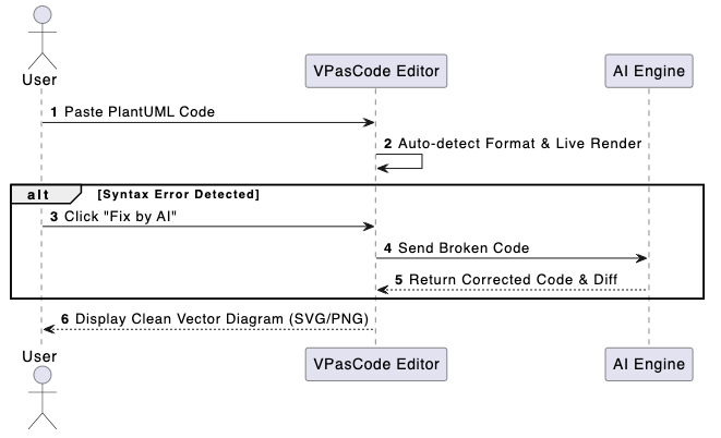
Simply copy the code above, open VPasCode, and paste it into the editor to view instant live rendering and experiment with automated AI enhancements.
7. Conclusion & Next Steps
PlantUML empowers teams to maintain clear, versionable, and consistent visual documentation across UML, architecture, database schemas, and project management charts. Paired with a modern PlantUML Tool like VPasCode, technical writing becomes faster, error-free, and seamlessly collaborative.
Ready to streamline your diagramming process? Start editing and rendering PlantUML diagrams for free today at vpascode.com.